
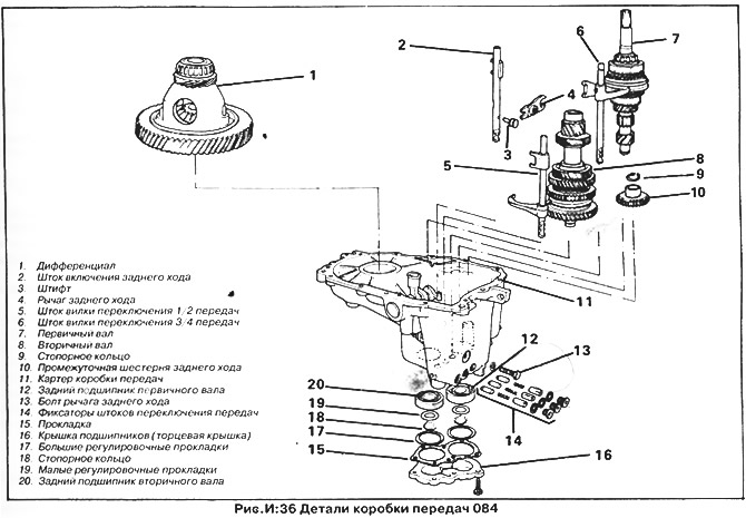
Gearbox disassembly (pic. I:36)
1. Drain the remaining oil from the gearbox and wash it with solvent.
2. Remove the clutch release bearing. Remove the outer sleeve of the clutch release shaft (1, fig. I:5), pull the shaft out of the inner sleeve and remove it from the clutch housing.
3. Remove the axle flanges (see section "Axle flange seals" this chapter).
4. Turn out bolts of fastening of a case of coupling. Make sure all bolts are removed, especially those inside the crankcase. Using a mallet, lightly tap around the clutch housing to transmission joint, separate the clutch housing by removing it from the dowel pins. It may be necessary to gently press the clutch housing with a lever
5. Remove the magnetic metal chip catcher from the bottom of the gearbox housing and clean the case of remaining chips
6. Remove differential (1, fig. I:36).
7. Turn the gearbox over with the rear end cap up. Unscrew the seven bolts securing the cover and remove it (16, fig. I:36).
8. Remove the bearing shims and circlip from the input shaft using circlip pliers and a thin screwdriver.
9. Make sure the shift rods are in neutral and all gears are out. Using a hex wrench, unscrew the plugs of the rod retainers together with the springs, bushings and plungers (14, fig. I:36).
10. Turn out the screw of the lever of inclusion of a backing located above plugs of clamps (13, fig. I:36). On later models, the screw is Phillips and is usually tight, so use an impact screwdriver to loosen it.
11. Turn the transmission over and pull out the stem and reverse gear lever. Be careful not to damage the dowel pins.
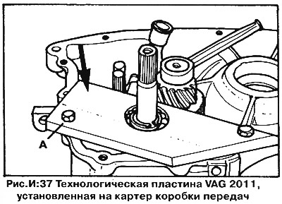
12. To remove the input shaft and its rear bearing, it is necessary to fix the front end of the shaft with a technological mounting plate (fixture VAG 2011), which you can buy or make yourself. Bolt the plate to the gearbox housing, installing washers to hold the input shaft stationary (fig.I:37).
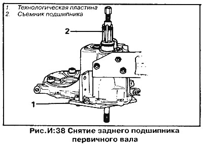
13. Pull the input shaft rear bearing out of the gearbox housing using a puller (pic. I:38), unscrew the bolts and remove the technological plate.
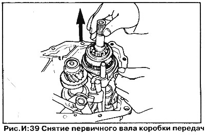
14. Move the shift pawl aside and secure it with a wire hook. Move the input shaft away from the secondary along with the yoke and 3/4 shift rod and remove the input shaft from the crankcase. In this case, the reverse gear must be lifted in order to pass the gear of the first gear of the input shaft past it (pic. I:39).
15. Remove the retaining ring and the bearing gaskets of the secondary shaft (18 and 19, fig. I:36).
16. Install a puller on the output shaft bearing and press the secondary shaft out of the bearing and out of the gearbox housing towards the clutch together with the 1/2 gear shift rod and fork.
17. Take out blocking crackers and springs from the case of a transmission.
18. Knock out the rear output shaft bearing from the gearbox housing with a soft punch.
Input shaft - disassembly (fig.I:44)
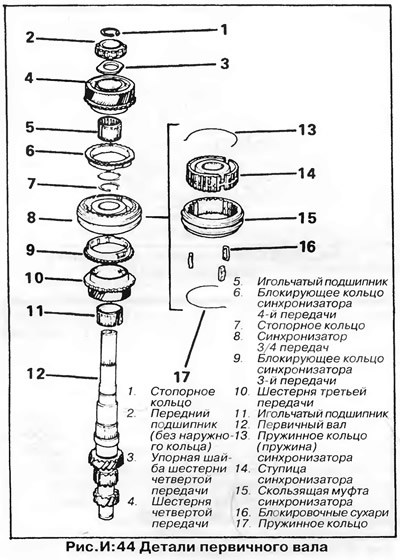
1. Remove the circlip from the spline (front) end of input shaft (1, fig. I:44). Remove the 4th gear front bearing and thrust washer (2 and 3, fig. I:44).
2. Remove the 4th gear together with the synchronizer ring and needle bearing (4 and 5, fig. I:44).
3. Remove the thrust washer and circlip of the 3/4 gear synchronizer (7, fig. I:44). Hooking the puller on the 3rd gear, pull the gear together with the 3/4 gear synchronizer (8, 9 and 10, fig. I:44). Separate the parts from each other, remove the third gear synchronizer ring and the needle roller bearing.
4. Clean and inspect parts as described in section "Inspection of gearbox parts". Check synchronizers (13-17, fig. I:44), as described in section "Synchronizers".
Output shaft - disassembly
1. Remove the pinion gear circlip and thrust washer (1, fig. I:40).
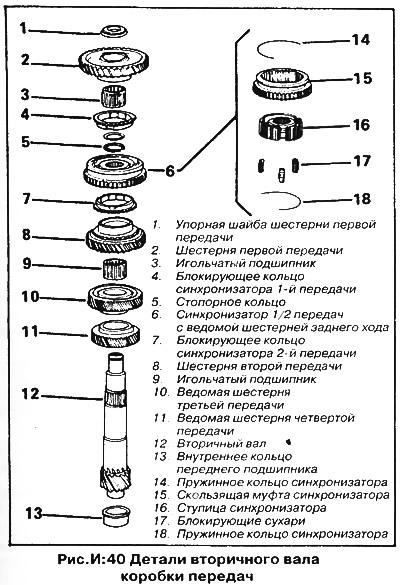
2. Remove the first gear, needle bearing and synchronizer ring (2, 3, and 4, fig. I:40).
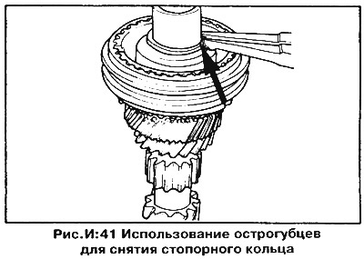
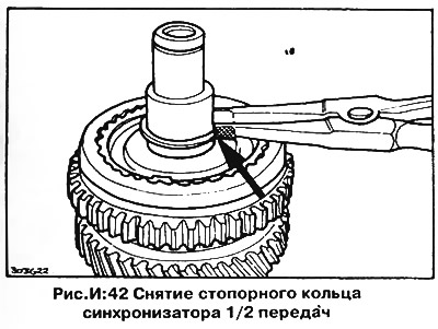
3. Remove the thrust washer and circlip of the 1/2 gear synchronizer (pic. I:42).
4. Grabbing the 2nd gear with a puller, pull the gear together with the 1/2 gear synchronizer (6, 7 and 8, fig. I:40). Separate the parts, remove the second gear synchronizer ring and the second gear needle roller bearing.
5. Clean and inspect parts as described in section "Inspection of gearbox parts". Check the synchronizers as described in section "Synchronizers".
Synchronizers - disassembly
1. Mark the mutual position of the hub and the sliding sleeve of the synchronizer.
2. Remove the spring rings, pull the hub out of the coupling and remove the crackers (14-18, fig. I:40).
3. Check the cleanliness of the surface of the internal splines of the hub and blocking crackers for wear or damage.
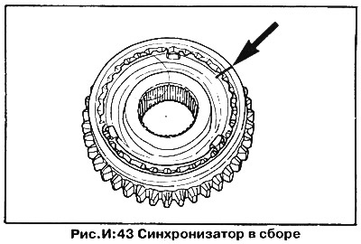
4. Put the sliding sleeve on the hub, aligning the previously made marks (pic. I:43).
5. The grooves in the inside of the coupling must align with the grooves for the nuts on the hub. The notch on the sliding sleeve must face the same direction as the groove on the side of the hub. The groove is on the side of the longer hub splines.
NOTE: There are no grooves or notches on the output shaft synchronizers.
6. Establish crackers and spring rings. The bent ends of the spring rings must be located in the grooves. Spring rings should be directed in opposite directions, and their bent ends should be separated at an angle of 120°.
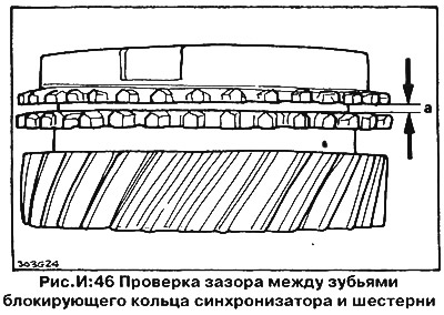
7. Check the locking rings by sliding them over the tapered surfaces of the corresponding gears and measuring the gap between the teeth of the ring and the gear with feeler gauges (pic. I:46). If the gap is less than 0.5 mm, replace the blocking rings.
Inspection of gearbox parts
Clean all parts and inspect them for wear and damage as follows:
1. Inspect all gear teeth for wear or chipping and all bearings (including thrust washer surfaces) for burrs, gouges or roughness. If the teeth are damaged, then the gear should be replaced (gear block) together with the blocking rings of the synchronizers.
2. Inspect the roll surfaces for wear or deterioration in surface hardness. Inspect the timing ring teeth for chipping or breakage, as well as the bevel surfaces and timing teeth on each gear. Check the condition of the taper surfaces of the gears and the synchronizer blocking rings by placing each ring on the cone of the corresponding gear and turning it while pressing it against the gear. Also check the clearance shown in fig. And: 46 - it should be at least 0.5 mm. If the blocking ring turns easily on the gear, this indicates wear on the conical surfaces. Retest with a new synchronizer ring to identify the defective part.
3. Check the ease of rotation of the ball bearings; inspect roller and needle bearings for pitting on the surface of the rollers, replace if necessary.
4. Check the operation of all clamps - that is, the condition of crackers and spring rings of synchronizers, blocking crackers and locks of gear shift rods; if necessary, replace the retainer springs.
5. Inspect the ends of the shift forks and compare their thickness with the thickness of the new forks.
6. Lubricate the working surfaces of all parts before assembly (synchronizer hubs, rings, cones, gears, etc.)
Input shaft assembly (pic. I:44)
1. Install the 3rd gear needle bearing and pinion onto the input shaft.
2. Install the 3rd gear synchronizer blocking ring onto the 3/4th gear synchronizer by inserting crackers into the ring grooves. Press the synchronizer onto the splines of the shaft using a puller or a metal tube. The groove on the side of the hub must face the 4th gear. Secure the synchronizer with a new thrust washer and circlip.
3. Install the fourth gear synchronizer blocking ring, aligning the grooves with the crackers. Remove the 4th gear needle bearing.
4. Put on the fourth gear and secure it with a new thrust washer and retaining ring, with the ring correctly positioned.
Output shaft assembly (pic. I:40)
ATTENTION: If the third and/or fourth driven gears require replacement, this work should be left to a VAG representative or a specialized company, since the gears must be heated to 120°C and installed with a special press.
1. Slide the 2nd gear needle bearing onto the output shaft and install the 2nd gear.
2. Install the 2nd gear synchronizer blocking ring on the 1/2 gear synchronizer, aligning its grooves with crackers.
CAUTION: The ring must be installed on the side of the reverse gear.
3. Press the synchronizer onto the splines using a puller or a metal tube, while the groove of the sliding sleeve should be on the side of the first gear.
4. Secure the synchronizer with a new circlip and install a new thrust washer.
5. Install the first gear blocking ring on the 1/2 gear synchronizer, aligning the grooves of the ring with crackers.
6. Install the first gear needle bearing, then install the gear. Install a new thrust washer and secure the gear with a new circlip.
Clutch housing (pic. I:45)
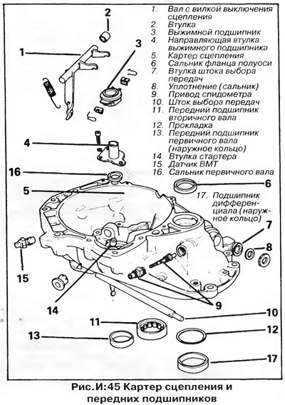
Clean the clutch housing and inspect it for damage or cracks. The clutch housing contains the driven gear of the speedometer drive, the gear selection rod and the front bearings of the primary and secondary shafts. If necessary, replace these parts as follows:
1. Remove the inner gear selector shaft seal, lubricate the new seal and press it into place evenly, without distortion, using a metal tube. To remove the stem, you need to unscrew the gearshift pin and pull out the stem (10, fig. I:45). Installation is carried out in the reverse order.
2. Turn out the sleeve of the driven gear of the speedometer drive and pull out the gear (9, fig.I: 45). Inspect the parts, especially the bushing, and assemble the speedometer drive in reverse order.
3. The outer rings of the front bearings of the primary and secondary shafts, as well as the starter bushing (11,13 and 14, fig. I:45) can be pressed out with a metal tube or knocked out with a suitable size drift after removing the appropriate seals.
4. Install bearings with new seals in order, (Reverse withdrawal. Lubricate the seals before installation.
NOTE: The input shaft seal should be recessed approximately 2.5mm below the crankcase surface.
Gearbox housing (fig.I:36)
1. Inspect the gearbox housing for damage and leaks.
2. Check pawl, shift lever and shaft, and shaft bushings for wear. If replacement is necessary, unscrew the bolt, remove the lever and pull out the shaft with the pawl. Knock out the bushings with a punch of the appropriate size. Lubricate the new bushings and press them into place with a mandrel. Install the shaft, pawl and lever in the reverse order of removal.
3. Inspect the reverse gear axle for excessive wear. If replacement is necessary, heat the axle mounting area in the gearbox housing with a blowtorch and knock the axle out of the housing. Press the new axle into the crankcase, preheating it (blowtorch or in a vessel of boiling water for several minutes). The end of the axle must be 83.3 mm from the outer surface of the crankcase.
4. Inspect the shift rods and forks (2, 5, and 6, fig. I:36) for wear, damage, or excessive play, replace if necessary.
Gearbox assembly 084
1. Install the output shaft bearing in the gearbox housing with the closed side inward.
2. Lubricate the rod locking keys and insert them into the crankcase. Move the shift pawl to the side with a wire hook, overcoming the resistance of the spring.
3. Install the fork with the shift rod 1/2 gears in the groove of the sliding synchronizer sleeve on the secondary shaft.
4. Slide the reverse idle gear onto the axle and hold it up with a wire hook.
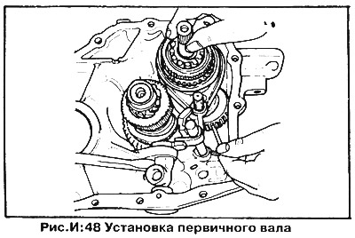
5. Lower output shaft with yoke and 1/2 gear rod into crankcase. At the same time, install the reverse gear over the first gear by lifting it up with a wire hook (pic. I:48). Make sure the shift rod is in the neutral position and the reverse gear can move freely.
6. After replacing the output shaft or its bearing, determine the bearing preload as follows:
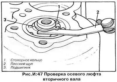
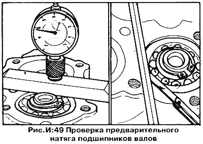
Install the bearing circlip and measure the clearance between the circlip and the bearing inner race with a feeler gauge (pic. I:47). Select the gasket so that the gap is 0-0.05 mm and install it under the retaining ring. Measure the gap between the crankcase surface (without gasket) and the outer ring of the bearing using a ruler and feelers or a special tool VAG No. 382/7 (pic. I:49). By adding 0.27-0.31 mm to the obtained value, you will get the thickness of a large shim, which must be installed on the outer ring of the bearing under the cover.
7. Install the fork and 3/4 shift rod into the groove of the synchronizer sliding sleeve on the input shaft.
8. Lower the input shaft with the yoke and shift rod into the crankcase and engage the gears with the output shaft gears. Raise the reverse gear to allow the input shaft first gear to pass.
9. Secure the input shaft with the service retaining plate, then remove the wire hook from the reverse gear.
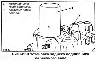
10. Press the input shaft rear bearing into the gearbox housing and onto the shaft using a metal mandrel (pic. I:50). The closed side of the bearing must face the inside of the gearbox.
11. Check, if necessary, determine the thickness of the large and small shims, and install them on the end of the input shaft, as described earlier for the output shaft.
12. Remove the technological plate from the input shaft.
13. Install the lever on the reverse engagement rod, then lower them into the crankcase and engage the lever with the reverse gear (in this case, the gears will need to be slightly raised).
14. Install the lever approximately 2.0mm from the 1/2 shift shaft and make sure the pin on the shaft is flush with the fork.
15. Install the reverse gear lever screw with a washer under its head and tighten it to the torque specified in section "Technical data". The gap between the reverse gear lever and the gearshift rod should be within 1.3-2.8 mm.
16. Insert the plungers, springs and retainer sleeves into the gearbox housing, then install the plugs with washers. Tighten the plugs with a hex wrench.
17. While moving the shift shaft lever, make sure that each gear engages easily. Make sure that two gears cannot be engaged at the same time.
18. Install large shims of the desired thickness on the input and output shaft bearings, then install the end cap with a new gasket.
19. Install differential.
20. Clean the mating surfaces of the gearbox and clutch housing. Install new gaskets.
21. Install the magnetic metal chip catcher in the groove of the gearbox housing.
22. Check the shift rods - they should be in the neutral position. Lower the clutch housing onto the transmission housing ensuring that the pin engages with the shift shaft lever.
23. Align the dowel pins, then insert the bolts and tighten them evenly in a diagonal sequence to the torque specified in section "Technical data".
24 Insert the axle flanges into the differential as described earlier in this chapter.
25. Install reverse light switch and shift/fuel consumption sensor (in the presence of).
26. Install the yoke shaft and clutch release bearing as previously described.
27. Establish a transmission in sequence, return to removal. Pour oil into the gearbox.
Visitor comments