
To remove and install the clutch, it is recommended to use two special tools:
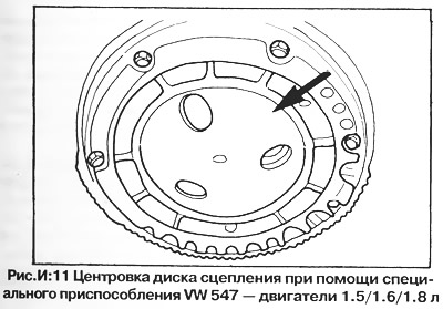
The first tool is designed to center the clutch disc relative to the flywheel (fig. I:11) and consists of a convex disc mounted in the bore of the flywheel, and a centering pin included in the hole in the hub of the clutch disc.
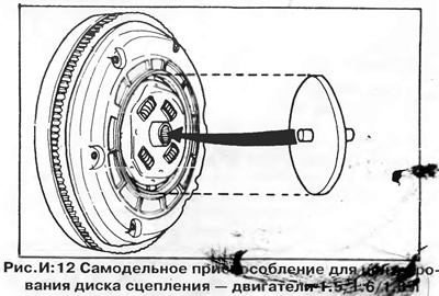
In the absence of a special device, you can center the disk by eye or make a wooden mandrel, shown in fig. I:12 The homemade wooden jig must exactly fit the bore in the flywheel and the hole in the hub of the clutch disc. The centering pin should be located exactly in the center of the disc.
When centering the driven disk by eye, ensure that there is an equal gap around the entire circumference between the inner edge of the flywheel and the outer edge of the hub of the clutch driven disk.
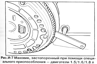
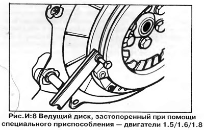
The second device is a stopper to prevent the flywheel and drive disk from turning when the mounting bolts are loosened (pic. I:7, I:8) A similar homemade fixture is easy to make from a metal plate and two suitable bolts.
Removing the clutch
Remove the transmission from the vehicle as described later in this chapter.
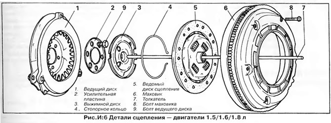
1. Mark the mutual position of the flywheel and the drive disk for their correct alignment during subsequent assembly.
2. Fix the flywheel with a screwdriver or a special stopper (pic. I:7) and loosen the six bolts securing the flywheel to the drive plate (8, fig. I:6). Loosen the bolts in a diagonal sequence, turning them a few turns at each stage.
3. Remove the flywheel and clutch disc from the drive disc (fig.I:6).
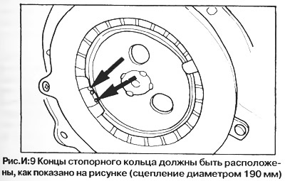
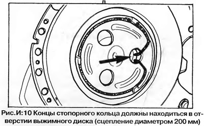
4. Squeeze out a lock ring of a vyzhimny disk (4, fig. I:6) and remove the release plate from the clutch drive plate. Before removing the retaining ring, mark the position of its ends (pic. I:9, I:10). On models with a five-speed gearbox of the type, the ends of the retaining ring are inserted into one of the holes in the release disk, and not under the tabs of the drive" about the disk, as on other models.
5. Inspect the drive disk without removing it from the crankshaft flange.
6. If the drive disc needs to be replaced, fix it (pic. I:8) and loosen six bolts (9, fig. I:6) fastening the disk to the crankshaft. Remove the disc carefully so as not to damage it.
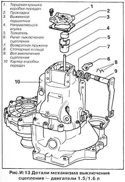
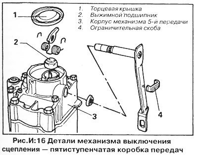
7. The clutch release mechanism is located at the end of the gearbox housing farthest from the engine and consists of a shaft, a clutch release lever, a release bearing and a pusher (pic. I:13). On the 5-speed transmission, the clutch release mechanism is located in the removable 5th gear housing (pic. I:16).
8. On a four-speed gearbox, remove the end cap from the gearbox, then remove the release bearing by turning the clutch release shaft. Install a new gasket when installing the end cap.
9. On models with a five-speed transmission, remove the end cover from the 5th gear housing by piercing and wringing it out. When assembling, a new cover is installed. Remove the stop bracket from the clutch release shaft lever so that the shaft can be freely rotated and the release bearing removed as described above.
10. Remove the retaining ring from the clutch release shaft (rings) and remove the shaft from the crankcase by removing the lever and return spring from the shaft.
Inspection
Inspect the clutch parts in the same way as described above for models with 1.1 / 1.3 liter engines.
NOTE: A 200 mm clutch can be installed in a repair in place of a smaller clutch, provided that the drive and driven disc assembly, flywheel, release plate and circlip are replaced.
Installation
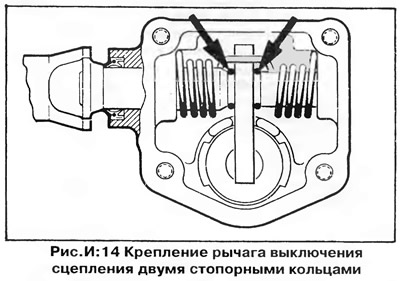
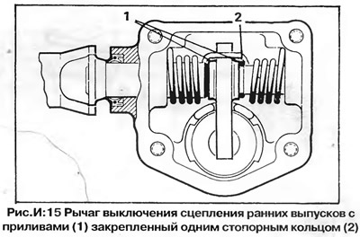
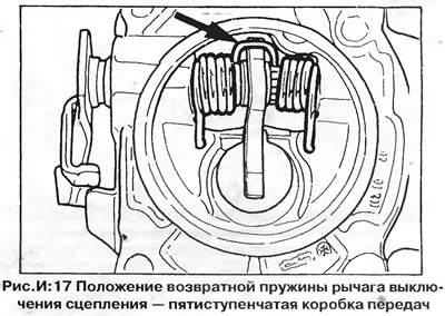
1. Assemble the clutch release mechanism in the reverse order of disassembly. On a four-speed transmission, install the clutch release lever return spring so that its bent ends touch the crankcase walls and the loop in the center of the spring engages the clutch release lever (pic. I:14, I:15). On early models, the lever is fixed with one retaining ring, on later models two rings are installed. On a five-speed transmission, install the ends of the return spring on the two tabs on the housing next to the release bearing hole (pic. I:16, I:17). The lever is fixed with two retaining rings
2. Install the release bearing in the gearbox housing and turn the clutch release shaft so that the lever rests on the bearing. On models with a five-speed transmission, install the limit bracket on the clutch release shaft lever. Install the end cap with a new gasket, or (on 5 speed gearbox) a new end plate, which must be carefully hammered into the socket.
3. Install the drive plate on the crankshaft flange. Lock disc (pic. I:8) and tighten the mounting bolts with a torque of 7.5 kgm (9, fig. I:6). Before installing the bolts, apply locking sealant to their threads. It is advisable to use new bolts.
4. Install the release disk and secure it with the circlip. Make sure the retaining ring and disc are in the correct position (pic. I:9, I:10).
5. Assemble the driven disc and flywheel on the clutch master plate, correctly orienting the driven disc relative to the flywheel (see marking on hub). Align the marks made on the flywheel and drive plate before removal. The dowel pins on the flywheel must align with the corresponding holes or slots in the drive plate, otherwise the TDC mark on the flywheel will be out of place.
6. Center the driven disk using the special tool as described above and tighten the flywheel mounting bolts. Tighten the bolts in diagonal sequence, a few turns at each step. Finally tighten the bolts to 2.0 kNm, then remove the centering tool.
7. Grease rubbing surfaces of a vyzhimny disk and a pusher with molybdenum greasing.
8. Install the gearbox as described below and adjust the clutch cable.
Visitor comments