
General information
The fifth gear mechanism of the Type 020 five-speed gearbox is mounted on the end of a similar four-speed gearbox. The following section describes the procedure for repairing the fifth gear mechanism, and then the four-speed gearbox as a whole. Additional work related to the five-speed gearbox is included in the text of the chapter describing the repair of the four-speed gearbox.
Fifth gear mechanism - removal (pic. I:57)
2. Pull off the rubber boot from the selector rod, remove the rod retainer (or stem screw, depending on type) and 5th gear lock. Remove the selector rod cover using a 14mm socket wrench (suitable candle wrench) and remove the selector rod assembly.
3. Drain the gearbox oil, loosen the left front wheel bolts and raise the front of the car (see chapter "Basic rules for work"). Remove the wheel.
4. Place a jack under the gearbox (installing a wooden gasket between it and the crankcase) and remove the two bolts securing the rear support bracket to the gearbox.
5. Lower the gearbox so that you can access the rear of it (located on the left side of the car). Remove the six bolts securing the 5th gear housing and remove the housing. Remove the clutch release bearing.
6. Engage fifth gear and reverse at the same time (To do this, push the front and rear selector forks towards the clutch housing) and with a 12 mm socket wrench, unscrew the bolt securing the fifth gear synchronizer hub.
7. Using a file or hacksaw, separate the spacer from the 5th fork guide tube and, using VW tool #3059, unscrew the tube from the 5th fork by turning it counterclockwise.
8. Remove the 5th gear synchronizer from the input shaft along with the gear, fork and thrust washer.
CAUTION: Do not remove the shift rod from the tube, otherwise the shift mechanism will fall apart inside the gearbox.
9. Remove the retaining ring securing the fifth gear to the output shaft, remove the thrust washer and carefully press the fifth gear off the shaft.
Repair
1. Remove the thrust washer from under the 5th gear, then separate the gear from its needle bearing.
2. Remove the sliding sleeve from the synchronizer hub, assemble the blocking crackers, wring out the tongues of the synchronizer hub lock plate and remove the two springs.
3. Install the blocking ring on the conical surface of the gear and measure the gap between the ring and the gear using feeler gauges. If the gap is less than specified in the section "Technical data", replace the ring.
4. Inspect the gear and needle bearing for wear or damage and replace as a pair if necessary.
5. Install the synchronizer hub inside the sliding sleeve so that the chamfer on the splines of the sliding sleeve faces towards the protruding part of the synchronizer hub. Align the grooves in the sliding sleeve splines with the dowel slots in the hub.
6 Install the blocking lugs in the cutouts of the hub (hollow side in), then install one of the springs by inserting its folded end into one of the locking lugs. Turn the synchronizer over and install the second spring so that the bent end of the spring is inserted into the cracker offset 120°from the end of the first spring.
7. Install the tabs of the lock plate into the notches of the hub and press the plate into place. Install the needle bearing on the protruding part of the synchronizer hub, then install the blocking ring, aligning the cutouts with the blocking biscuits.
8 Install the fifth gear onto the bearing, then the thrust washer (chamfer from the gear) onto the protrusion of the synchronizer hub and insert the 5th gear fork into the groove of the sliding sleeve.
9. Check the output shaft needle bearing for wear, replace if necessary as follows:
Loosen the mounting screw, heat the crankcase in the bearing area to 80°C and tap the crankcase against a wooden stand to dislodge the bearing Keeping the crankcase at 80°C, install the new bearing in place using VW No. 2448 in combination with VW 455. Install the mounting screw.
Installation and adjustment (pic. I:58)
1. Heat the fifth gear driven gear to 100°C and install it on the secondary shaft with the groove from the gearbox. Install the small thrust washer and a new circlip.
2. Install a new spacer on the 5th fork, then install the fork on the shift shaft while sliding the synchronizer with the 5th gear and thrust washer onto the input shaft.
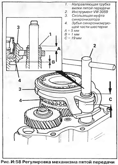
3. With the shift rod fixed, screw the guide tube into the 5th gear shift fork by turning it clockwise using tool VW 3059. The tube should protrude 5 mm above the fork surface.
4. Engage fifth gear and reverse at the same time as described above, apply a thin layer of sealant "Loctite" on the threads of the new synchronizer hub bolt, then screw in the synchronizer hub bolt and tighten to the required torque using a 12 mm slotted wrench.
5. Move the selector forks to neutral, then install the selector rod assembly, spring, and cover. Install and adjust the 5th gear retainer and selector rod retainer, then attach the shift actuator.
6. The guide tube should protrude 5 mm above the fork; if not, adjust the tube position with tool VW3059. Engage fifth gear from the passenger compartment with the gearshift lever. Slide the 5th fork away from the gearbox to select the play and make sure the synchroniser sliding sleeve overlaps the synchronizing gear teeth by 1.0mm.
7. Using tool VW3059, rotate the fork guide tube until it protrudes 5 mm from the fork. rivet (nick) spacer in two places 19 mm below the top edge of the guide tube.
NOTE: After riveting the bushing, the shift rod should pop out automatically when pressed, under the action of the spring.
8. Insert the clutch release bearing, then install the 5th gear housing to the gearbox. Install and torque the body bolts to the correct torque - see section "Technical data" (two short bolts are installed one at a time on both sides of the filler plug).
9. Lift a transmission, screw in bolts of fastening of a transmission to a back basic arm and tighten them with the demanded moment. Install the wheel and lower the car to the ground.
10. Fill the gearbox with the correct brand of oil in the correct quantity. Place the shift lever in neutral position.
5th gear lock
The 5th gear lock is located on top of the gearbox housing near the reverse light switch and shift rod lock. Adjust the detent if too little or too much force is needed to engage fifth gear.
1. Turn off the gear and remove the plastic cap from the retainer.
2. Loosen the jam nut and turn the bushing until the plug starts to move up out of the bushing. Loosen the sleeve 1/3 turn, tighten the locknut and install the cap on the retainer.
Removing the gearbox housing
1. Remove the gearbox from the vehicle and drain the oil. Make sure the gears are in neutral and remove the clutch pusher from the input shaft.
2. Install the VW 30211A fixing rod across the clutch housing so that the bolt in the middle of the rod is opposite the input shaft. Place a VW 295A thrust pad under the bolt and tighten the bolt so that the thrust pad is firmly pressed against the input shaft. Tighten the bolt locknut.
3. Turn away a nut and disconnect the lever from a rod of a choice of transfers. Pull off the rubber boot of the gear selector rod, remove the fastening screw or rod retainer, fifth gear retainer (in the presence of) and reverse light switch. Unscrew the selector rod cover using a 14 mm wrench. Remove the oil deflector, spring and remove the gear selector rod assembly.
NOTE: The gear selector stem cannot be removed while any gear is engaged.
4 Remove the plastic cover from the axle shaft flange on the gearbox side and release the circlip. Remove the Belleville washer and install the VW391 tool or puller on the flange. Screw in the puller bolt and remove the flange.
5. Turn out bolts of fastening of a back end cover (on a four-speed gearbox) or 5th gear housing (on a five-speed box) and remove the cover (frame).
6. Remove the clutch release shaft (on a four-speed gearbox). Remove the shaft from the gearbox housing by removing the clutch release lever and return spring.
7. Remove the clutch release bearing and fifth gear parts as described above (on a five-speed gearbox).
CAUTION: Do not pull the shift rod out of the 5th fork guide tube, as otherwise the shift mechanism will fall apart inside the gearbox. Loosen the screws securing the input shaft bearing lock plate with a 5mm hex wrench.
8. On gearboxes of both types, unscrew the bolt securing the reverse idler gear shaft, which is located at the bottom of the gearbox housing, then remove all the bolts securing the gearbox housing to the clutch housing. Pay attention to the position of the bracket for the intermediate gear selector lever.
9. Install tool VW 3042 across the rear of the gearbox so that the pointed end of the tool bolt aligns with the end of the input shaft.
10. Install the VW3042 thrust pad on the input shaft (on a four-speed gearbox) or on a bolt (on a five-speed gearbox). Make sure the locknut is in the cutout in the tool base. Tighten the bolt until the gearbox housing separates from the clutch housing.
11. Remove the crankcase and assemble the three bearing holders (on a four-speed gearbox) and shims that may fall out of the input shaft bearing housing (on gearboxes of both types).
Crankcase repair
1. If the gearbox housing is being replaced, transfer the filler plug, differential bearing outer race and needle to the new housing (rear) output shaft bearing (if they are in good condition). Adjust differential bearing preload.
2. Check the condition of the secondary shaft needle bearing (located in the gearbox housing) for wear or damage, replace if necessary as follows:
Remove the bearing fixing screw, heat the gearbox housing to 80°C and tap the housing against a wooden stand to dislodge the bearing. Keeping the crankcase temperature at 80°C, install the new bearing using tools VW 2015 and VW 40503. Secure the bearing with the screw.
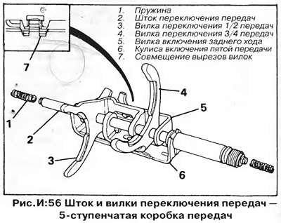
3. Inspect the parts of the shift mechanism and gear selector rod (pic. I:55 and 56) for wear or damage, if necessary, disassemble it as follows:
On four-speed transmissions with a selector rod retainer, remove the circlip; if there is no retainer, a retaining ring and a pin. On both types of gearboxes, knock the stem out of the link and pin with a suitable drift fitted to the smooth end of the stem. Remove pin from stem (with a retainer) or pin, spring and detent disc (in the absence of a separate plunger rod lock).
On five-speed transmissions with a selector rod plunger, remove the circlip, spring disc, spring, clutch, and second circlip. Knock out the stem from the pin and backstage with a suitable drift.
On five-speed transmissions without a rod retainer, remove the circlip, spring disc, spring, and second circlip. Remove the pin and knock the stem out of the pin and backstage with a suitable drift. Remove pin, detent disc and spring.
4. Reassemble in reverse order. On transmissions with a selector rod plunger, place your finger inside the yoke, then insert the selector rod and secure it with the circlip. On five-speed transmissions, also install the clutch, spring, spring disc and remaining retaining ring on the rod.
On gearboxes not equipped with a stem lock plunger, place the lock disc with spring and pin inside the yoke, then insert the stem (the hole in the stem must align with the hole in the pin) and secure the pin to the stem with a pin. Install retaining ring. On five-speed transmissions, also install the clutch, spring, spring disc and second circlip.
NOTE: Before reassembling the transmission case, fill the space between the sealing lips of all oil seals with multipurpose grease.
Crankcase installation
1. Remove the circlips from the input and output shafts. Engage the input shaft 4th gear with a puller and pull the bearing, lock plate and gear off the input shaft while sliding the 4th driven gear off the output shaft. Slide the 4th gears back onto their respective shafts and install a new circlip onto the output shaft.
2. Install the input shaft bearing washer (in the presence of) into the gearbox housing and press the bearing (the protruding part of the inner race to the fourth gear) into the crankcase. Install the bearing retainer plate, tighten the nuts to the torque specified in section "Technical data".
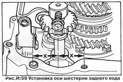
3. Make sure the reverse idler shaft is installed correctly (distances "X" the same - Fig. I:59). Install the fixing rod (fixture VW 30211) and hard lining (fixture VW 295A) under the main shaft. Install the gearbox housing and screw in a few bolts as guides. Tap the gearbox housing onto the clutch housing with a soft hammer (mallets).
4. Screw in the reverse idler gear shaft mounting bolt and tighten it to the torque specified in section "Technical data". Ensure that the two short bolts are installed near the shift housing and the selector bracket is correctly positioned, and tighten the transaxle housing bolts to the correct torque.
5. Move the shift forks to neutral, rotate the transmission so that the shift housing is vertical, and insert the selector rod assembly. Install the spring and oil deflector (only on 4 speed box) concave surface inwards, install and tighten the stem cap Install the selector stem rubber boot and reverse light switch. Install and adjust the stem retainer or screw in and tighten the stem retaining screw (depending on the type). Install and adjust the 5th gear lock (in the presence of).
6. On four-speed gearboxes, check the tightness of the bearing mounting nuts and install two rubber plugs. Install a new circlip on the input shaft. Install the lever, return spring and clutch release shaft and secure the shaft with two circlips.
NOTE: The release shaft is splined to ensure that the lever is in the only correct position.
7. On five-speed transmissions, check the tightness of the bearing retainer plate screws using a 5mm hex wrench. Install and adjust the parts of the fifth gear mechanism as described above; reinstall the clutch release bearing and fifth gear housing with end cap
8. On four-speed transmissions, install the clutch release bearing and bushing, then reinstall the rear end cap. Screw in the bolts and tighten them to the torque specified in section "Technical data".
9. Install the VW 391 fixture on the axle shaft flange, screw the fixture bolt into the axle shaft and, turning the fixture nut, press the flange onto the axle shaft. Install the Belleville washer with the concave surface inward, then install a new circlip and plastic cover. Attach the gear selector lever to the stem and tighten the nut.
ATTENTION: Do not try to hammer the flange onto the axle shaft with a hammer - this will damage the axle of the differential pinions.
10. Remove the fixing rod and thrust pad and insert the clutch pusher into the input shaft.
Disassembly of the gear shift mechanism (pic. I:55 and I:56)
1. Set the transmission gears to neutral and remove the clutch pusher from the input shaft.
2. Install the fixing rod VW 30211 and the thrust pad VW 295A, fix the input shaft and remove the gearbox housing (on four-speed gearboxes).
3. On five-speed gearboxes, remove the housing and parts of the 5th gear mechanism, as described earlier, as well as the clutch release bearing. Remove the gearbox housing and pull the shift rod out of the clutch housing along with the forks, disengaging the forks from their respective synchronisers.
4. On four-speed gearboxes before removing the stem; Remove the two circlips securing the forks to the shift shaft. Remove the rod from the clutch housing, disconnect the forks from the synchronizers and remove the mechanism assembly.
5. Remove the two bolts securing the reverse gear lever struts to the clutch housing and remove the struts and lever.
Gear shift mechanism repair (pic. I:55 and I:56)
1. On five-speed transmissions, remove the springs from both ends of the shift shaft, then remove from the fork shaft.
2. On four-speed transmissions, slide the forks off the stem.
3. On both types of units, inspect the stem for wear and replace if necessary. «Inspect the forks for wear, distortion or cracks and replace if necessary.
4. On four-speed gearboxes, when assembling the mechanism, remember that the pin of the reverse gear fork must fit into the slot of the 1/2 gear shift fork.
5. On five-speed transmissions, the fifth gear pin fits into the 3/4 shift fork slot, and the reverse shift fork pin fits into the 1/2 gear shift fork slot (the fork differs in the recesses and outer edges of the teeth).
6. On four-speed transmissions, insert the shift rod (grooves for retaining rings downwards) into the forks so that the grooves are on both sides of the 1/2 gear fork from the side of the fork teeth.
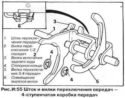
NOTE. The correct assembly of the forks on the stem is determined by the alignment of the cutouts in the fork plates (6, fig. I:55, insert).
7. On five-speed transmissions, assemble the forks and insert the shift rod into them. Install on both ends of the spring rod.
ATTENTION: The correct assembly of the forks on the stem is determined by the alignment of the cutouts in the fork plates and the 5th gear backstage (7, fig. I:56, insert).
8. Inspect the reverse gear lever and its struts for wear and damage, replace defective parts if necessary.
Installing the gearshift mechanism
1. Insert the forks into the grooves of the sliding sleeves of the corresponding synchronizers and insert the shift rod into the clutch housing.
2. On four-speed transmissions, locate the circlip grooves on both sides of the 1/2 shift fork and install the circlips on the stem.
3. Install the reverse gear lever and its rack so that the forked end of the lever engages the reverse idle gear and the flat end engages the reverse gear fork. Adjust the position of the uprights so that the arm can turn freely without axial play. Install and tighten the bolts to the torque specified in section "Technical data".
4. Establish an axis of an intermediate gear wheel of a backing, as it is shown in fig. I:59 (with equal distances "X"). Make sure that the fixing rod VW 30211 and thrust pad VW 295A are correctly installed and install the gearbox housing.
5. On five-speed transmissions, install and adjust the fifth gear mechanism as described above. Install the clutch release bearing, then install the 5th gear housing with end cap.
6. Remove the fixing rod and thrust pad and insert the clutch pusher into the input shaft.
Removing the gearbox shafts
1. Remove the gearbox housing and remove the shift rod assembly with forks as described above.
2. Remove the reverse idle gear and its shaft, remove the gear travel stop from the bearing retainer plate. Remove the magnet from the clutch housing.
3. Remove the retaining ring holding the fourth gear of the secondary shaft, then remove the input shaft and the driven gear of the fourth gear from the secondary shaft at the same time. If the driven gear is tight on the output shaft, use a puller.
Shaft repair
1. Check the reverse idle gear and its axle for wear, damage or distortion; inspect the gear travel stop and reverse lever plastic bushings. Replace defective parts if necessary. Clean the magnet.
2. Inspect the input shaft front bearing for wear or damage, replace if necessary as follows:
3. Remove the oil seal and, using a suitable mandrel and a press, press the bearing from the clutch housing side. Press in the new bearing so that it rests on the collar, then press in the new oil seal. Remove the retaining ring from the input shaft, hook the puller on the fourth gear drive gear and pull the gear and bearing off the shaft (on five-speed gearboxes - also a bearing retainer plate).
4. Remove the 4th gear needle bearing and release the circlip holding the 3/4 gear synchronizer.
5. Press the 3rd gear and 3/4 synchroniser assembly off the shaft, then remove the 3rd gear needle bearing from the shaft.
6. Remove the retaining ring holding the third gear on the output shaft and, using a puller, pull the second and third gears off the shaft. Remove the 2nd gear needle bearing and thrust washer.
7. Engage the first gear with a puller and pull the needle bearing, 1/2 gear synchronizer and first gear from the shaft. Remove the 1st gear needle bearing and thrust washer.
8. Inspect the parts of the secondary and primary shafts for wear and damage, replace parts if necessary.
CAUTION: The final drive and driven gears are a matched pair, so if the output shaft is replaced, the final drive driven gear must be replaced.
9. Inspect all gears and bearings for wear and damage and replace defective parts if necessary.
ATTENTION: Gears of the third and fourth gears cannot be replaced separately - only in pairs.
10. Install the synchronizer lock rings on the conical surfaces of the corresponding gears and measure the gap between the ring and the gear using feeler gauges (rice. I:46). If the gap is less than specified in section "Technical data", replace the ring. Check sliding sleeves and synchronizer hubs for wear and damage, replace as a set if necessary
11. Install thrust washer (groove on the inner edge towards the final drive gear) onto the output shaft, then install the gear and needle bearing of the first gear. Install the first gear lock ring.
CAUTION: Factory Installed 1st Gear Lock Ring (determined by three missing teeth - 7, fig. I.60), not supplied in spare parts. If this ring needs to be replaced, use a standard ring similar to the rings for other gears.
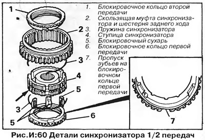
12. Install 1/2 gear synchro hub (determined by the gaps of the splines around the circumference) inside the sliding sleeve. Identification groove in the end surface of the hub (shown by the arrow in Fig. I:60) must face away from the groove on the clutch for the shift fork. The slots for crackers in the splines of the sliding sleeve must be aligned with the grooves on the hub.
13. Install blocking biscuits (hollow side in) into the grooves of the hub and insert one of the springs by inserting its bent end into one of the blocking crackers. Turn the synchronizer over and install the remaining spring so that its bent end is inserted into the cracker located at an angle of 120°from the bent end of the second spring.
14. Heat the synchronizer to 120°C and install it on the secondary shaft so that the identification groove in the end face of the hub faces the first gear.
15. Align the cutouts of the locking ring of the first gear synchronizer with the locking crackers. Finally press the synchronizer into place.
16. Heat the second gear bearing inner race to 120°C and press it onto the output shaft using a suitable mandrel. Install needle bearing, second gear lock ring (aligning the cutouts of the ring with the synchronizer crackers) and second gear.
17. Press the driven gear of the third gear onto the secondary shaft (ledge down).
Install a new retaining ring of the same thickness as the one removed. Measure the clearance between the gear and the retaining ring with a feeler gauge. Compare the gap with the value given in section "Technical data", if necessary, select a circlip of a different thickness to bring the third gear end play to the specified tolerance. Install retaining ring.
18. Install the third gear and needle bearing on the input shaft, then install the third gear lock ring. Install the 3/4 synchroniser hub into the sliding sleeve so that the dowel grooves in the sliding sleeve splines align with the grooves in the hub. Install the locking keys and synchronizer springs as described above (pic. I:61).
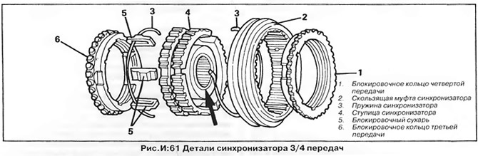
19. Heat the synchronizer to 120°C and install it on the input shaft so that the identification groove on the protrusion of the hub (shown by the arrow in Fig. I:61) facing the 4th gear.
20. Align the cutouts of the third gear blocking ring with the synchronizer blocking crackers. Finally press the sliding sleeve and synchronizer hub into place and install a new circlip.
21. Install the 4th gear lock ring (aligning the cutouts with the blocking biscuits), needle bearing and fourth gear.
Shaft installation
1. Install the input shaft in the clutch housing, and at the same time - the driven gear of the fourth gear (ledge up) with retaining ring on the output shaft.
2. Make sure the support rod is properly installed (accessories VW 30211) and install the thrust pad on the end of the input shaft (fixture VW 295A). Install the magnet in the clutch housing and the reverse gear travel stop on the bearing retainer plate. Install the reverse idler gear and its axle.
3. Install shift shaft and fork assemblies. On four-speed transmissions, install circlips on the stem.
4. Install the input shaft bearing washer (in the presence of) into the gearbox housing and press the bearing (the protruding part of the inner ring towards the fourth gear).
5. On four-speed transmissions, install the holders (locking plates) bearings and washers. Screw on the nuts and tighten them to the torque specified in section "Technical data".
6. On five-speed gearboxes, install the bearing lock plate, insert the mounting bolts and tighten them to the required torque.
7. Install the gearbox housing, making sure the reverse idle gear axle, service support bar and thrust pad are in the correct position.
Remove the support rod and thrust pad; insert the clutch pusher into the input shaft.
Visitor comments