



If necessary, disconnect the hoses from the air filter. Unscrew the three bolts securing the right rear engine mount bracket. Using a garage crane, lift the power unit. Remove the starter.
Set the selector lever to position "P" and disconnect the selector lever cable from the gear shift lever and rod.
Remove the clamp from the selector lever cable stop and disconnect the cable from the selector lever.
Remove the entire left powertrain mount bracket.
Disconnect the oil lines from the gearbox and plug the openings of the oil lines and gearbox.
Remove the protective oil pan of the gearbox. Remove the entire front bracket of the powertrain suspension.
Remove the anti-vibration weight.
Loosen the bolts securing the inner joints of the front wheel drive shafts from the flanges of the differential output shafts.
Remove the front protective cover of the timing belt. Remove the protective pan of the torque converter, unscrew the nuts securing the torque converter. Turn the gearbox towards the front of the car. Turn the front wheels to the left as far as possible. Raise the left wheel drive shaft assembly and secure it. Working from underneath the car, unscrew the lower bolts securing the gearbox to the engine block.
Disconnect the gearbox from the engine, separating the torque converter from the drive flange. Turn the gearbox and carefully remove it through the bottom of the car, making sure that the torque converter does not fall out.
The gearbox is installed in the reverse order of removal, taking into account the following:
- when installing, ensure that the adjusting bushings are in the correct position;
- check the adjustment of the selector lever cable and adjust it if necessary.
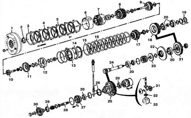
Fig. 4-75. Details of the automatic transmission type 096:
1 - torque converter;
2 — oil seal;
3 - retaining ring;
4, 15 - discs with internal engagement;
5, 16 — discs with external engagement;
6, 12 — drum;
7 — reverse clutch;
8, 9 — forward clutches;
10 — input shaft;
11 - crown gear;
13 — 1st gear freewheel clutch;
14 - pressure spring;
17 — satellite carriage;
18 — main gear drive pinion;
19 - screw plug;
20 — bearings;
21 — driven gear of the main transmission drive;
22 — housing of the rear bearing of the main gear drive shaft-pinion;
23 - parking brake toothed retaining ring;
24 — main gear drive shaft;
25 — driven gear of the main transmission;
26 — speedometer drive;
27 — differential box bearing adjusting nut;
28 — differential output shaft;
29 — differential output shaft flange seal;
30 — differential output shaft flange;
31 - semi-axial gears;
32 - satellites;
33 - satellite cup.
The original material is available on the portal VWManual
Visitor comments