
Removing
1. Remove output shaft from clutch housing. To do this, unscrew the bolts of the large front bearing lock plate and remove the plate along with the outer bearing race.
2. Remove a plastic cover from a flange of the right semiaxis, release a lock ring and remove a plate washer.
3. Remove the flange using VW 391, then remove the differential from the final drive gear.
Disassembly (rice. I:57)
1. Remove the two circlips holding the axle shafts and pull them out of the differential case.
2. Remove one of the circlips holding the pinion axle, knock the axle out of the body. Remove the pinion gears and side gears and remove the plastic thrust plate.
3. Inspect the satellites, gears, half shafts, the axis of the satellites and the thrust plate for wear and damage, replace worn parts if necessary.
4. Check the presenter (located on the secondary shaft) and final drive gear for wear or damage, replace if necessary.
ATTENTION: Replace final drive gears only in pairs.
5. If it is necessary to replace the final drive gear, proceed as follows:
Drill pilot holes with a thin drill along the axis of the rivets from the side of the countersunk heads, then drill the rivets finally with a 12 mm drill bit. Knock out the rivets and press the differential housing out of the final drive gear using a press.
6. Heat the new final drive gear to 100°C, install the two bolts as guides and press the gear onto the differential housing (chamfer towards the body). Install the remaining bolts, lock plates and nuts from the repair kit and tighten them to the torque specified in section "Technical data".
7. Inspect output shaft bearings and differential thrust bearings for wear and damage and replace if necessary.
8. Install thrust pad (fixture VW 295) on the differential housing and remove the bearing using a suitable puller.
9. Remove the second bearing from the differential in the same way. Remove both axle shaft seals from their sockets using tool VW681 and remove the bearing outer races using tools VW 295 and VW 554.
WARNING: There are shims under the outer races of the bearings. The outer and inner races of each bearing are matched to each other and are not interchangeable.
10. Using a puller, remove the large and small front bearings of the secondary shaft.
11. Remove the small bearing outer race from the clutch housing using tool VW 510 and remove the shim.
CAUTION: Large bearing outer race and lock plate must be replaced as an assembly. Do not attempt to press the outer ring out of the retainer plate.
Output shaft front bearing preload
1. Heat both output shaft bearings to 120°C and press them onto the shaft.
2. Lubricate the bearings with gear oil, install a 0.65mm shim into the small bearing outer race seat and press the outer race into place using a suitable drift.
3. Check the condition of the lock plate bolts and replace if necessary. Install the output shaft and lock plate with the large bearing outer race and tighten the bolts to the torque specified in section "Technical data".
4. Screw in adapter (VW 294b/3) into one of the bolt holes in the clutch housing (pic. I:62), set the heel (fixture VW 385/17) on the end of the secondary shaft and install the dial indicator with the rack (fixture VW 387) on the adapter so that its probe rests on the heel and is recessed by 1.0 mm (on the indicator scale). Slide the shaft longitudinally within the bearing play and note the indicator reading.
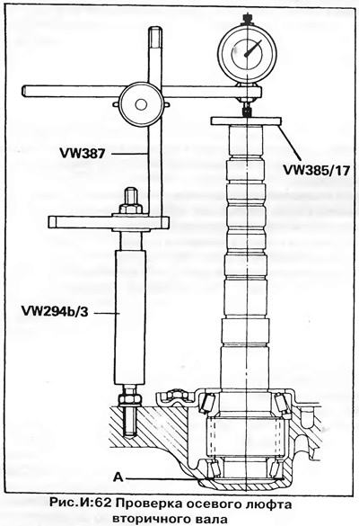
CAUTION: Do not rotate the shaft or you will get incorrect readings.
5. Add to the value obtained 0.65 mm (installed gasket thickness) and 0.20 mm (required preload value). Select a shim pack of this thickness (standard sizes of shims are given in the section "Technical data").
6. Pull the small bearing outer race out of the clutch housing using tool VW 554, then remove the gasket.
7. Place a thickness-matched shim pack into the small bearing outer race seat and press in the outer race with a drift.
8. Establish a secondary shaft and tighten bolts of fastening of a lock plate with the demanded moment.
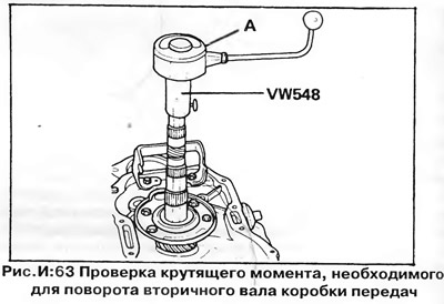
9. Attach the adapter to the shaft (fixture VW 548) and a torque meter. Measure the torque required to turn the output shaft and compare it with that specified in section "Technical data" (pic. I:63).
10. By increasing or decreasing the thickness of the gasket package, achieve the required torque value, then remove the output shaft.
Differential Assembly
1. Heat the differential bearings to 120°C and press them onto the differential housing.
2. Lubricate the gears, pinions, axle shafts and thrust plate with gear oil and insert the thrust plate into the differential housing.
3. Install the pinion gears and side gears of the differential inside the housing, press the pinion shaft into place and install the circlip.
4. Insert one of the axle shafts (threaded hole - to the outside).
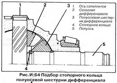
5. Press the axle shaft against the pinion shaft, and the side gear against the thrust plate and housing, and install the thicker of the two circlips on the axle shaft (pic. I:64). If, after installing the ring, the gear is pinched, remove the ring and install a thinner one. Repeat this operation on the other gear and axle shaft.
Differential support bearing preload
1. Lubricate the bearings with gear oil, install a 1.0 mm thick shim into the differential bearing outer race seat in the clutch housing, and press in the outer race using a suitable drift.
2. Install the differential on the clutch housing and press the outer race of the second differential bearing without gasket into the gearbox housing using tool VW 510.
3. Install the gearbox housing with a new gasket on the clutch housing and secure it with five equally spaced bolts, tightening them to the torque specified in section "Technical data".
4. Attach a dial gauge (pic. I:65) to the rack (fixture VW 387). Fasten the rack with the indicator on the gearbox housing and install the VW 385/17 heel on the axle shaft.
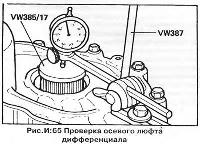
5. Install the dial indicator probe on the heel with an interference fit of 1.0 mm. Slide the differential longitudinally within the bearing play and record the indicator reading.
WARNING: Do not turn the differential or axle shaft or you will get an incorrect indicator reading.
6. Add 0.40 mm of play to the value obtained - the result is the required thickness of the shim. Select a shim pack of the correct thickness from the range shown in section "Technical data".
7. Remove the gearbox housing, remove the outer ring of the bearing installed without a gasket from it and install a selected package of gaskets under the ring (install the thickest spacer first).
8. Press the outer ring into place using tools VW 295 and VW510 Install the gearbox housing with gasket on the clutch housing and secure with five equally spaced bolts; tighten the bolts to the torque specified in section "Technical data".
9. Screw the bolt of tool VW382/3 into one of the axle shafts. Install a torque meter on the axle shaft (pic. I:66).
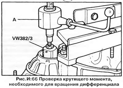
10. Lock the second axle shaft from turning and measure the torque required to turn the differential. If the result is not within the limits specified in section "Technical data", change the thickness of the shim pack to obtain the required torque.
11. Remove the differential from the housing and install new axle shaft seals using tool VW 194.
Installation
1. Insert the differential into the clutch housing, install the output shaft and tighten the lock plate mounting bolts to the torque specified in section "Technical data".
2. Continue assembling the gearbox as described above.
Visitor comments