
Digifant ignition and injection system (4-cylinder petrol engine)
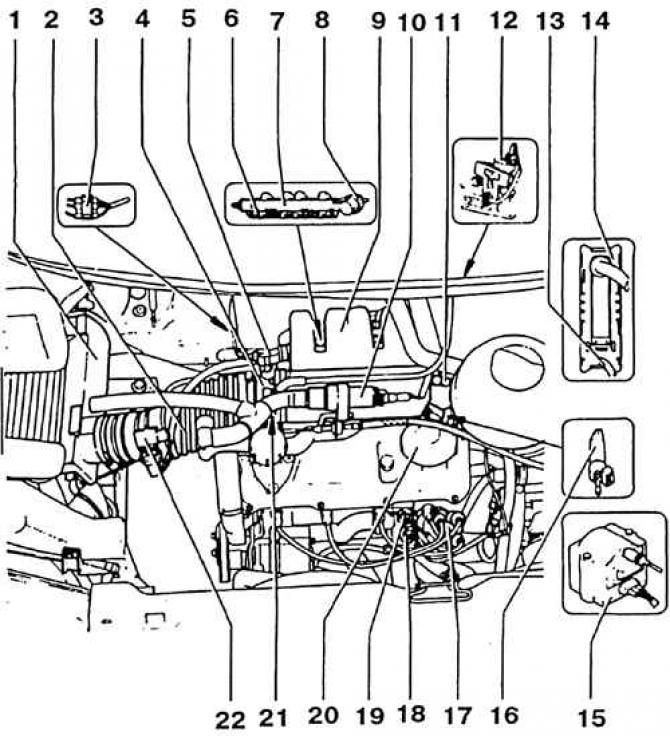
1. Air filter. With adjustable intake air heating damper; 2. Intake air duct; 3. Plug connection for lambda probe and lambda probe heater. Installation location: on the console of mounted units, on the right in the direction of travel; 4. Throttle pipe; 5. Throttle valve potentiometer; 6. Injection valve; 7. Fuel distributor; 8. Fuel pressure regulator; 9. Intake manifold; 10. Idle stabilization valve; 11. Cork. In the measuring tube CO; 12. Magnetic valve 1 tank with activated carbon. (As additional equipment); 13. Vacuum pipeline; 14. Digifant control unit; 15. High voltage transformer (ignition coil); 16. Cold start valve (up to 5/93 g); 17. Ignition distributor; 18. Coolant circulation thermostat with coolant temperature sensor temperature gauge; 19. Coolant temperature sensor. Blue, 2-pole Digifant; 20. Pressure control valve for crankcase ventilation; 21. Idle speed adjustment screw (up to 5/93 g); 22. Intake air temperature sensor. With CO potentiometer and CO adjustment screw (up to 5/93 g)
Attention! The 5-cylinder engine since January 1993, and the 4-cylinder engine since June 1993, have no idle and CO content adjusting screws.
Idling and CO content are checked simultaneously.
1. Interrogate memory, repair if necessary. Memory interrogation can only be performed by the VW-1551 reader unit. To do this, the measuring unit is connected with diagnostic plugs to two diagnostic sockets in the fuse box.
2. Warm up the engine in motion to an oil temperature of at least 80°C.
3. Turn off all electrical consumers. Turn off the air conditioner.
4. Check ignition timing (see subsection 2.14.5).
5. Check the tightness of the exhaust gas system.
6. Verify that the idle speed control valve is working. To do this, turn on the ignition and put your hand on the valve. It should vibrate and buzz. The valve is located above the cylinder head next to the throttle valve.
Attention! Connect control devices only when the ignition is switched off.
7. Connect the block for measuring revolutions (tachometer) according to instructions. As a rule, the tachometer is connected to terminal 1 and terminal 15 of the ignition coil.
8. Connect the CO measurement unit to the CO measurement tube in the engine compartment. The gauge tube is screwed to the exhaust manifold and is usually covered with a light blue cap.
Attention! The metering unit hose must be tight. Ensure that there are no exhaust gas leaks.
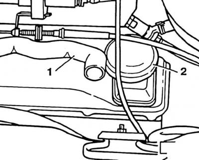
9. Disconnect the crankcase ventilation hose (1) from pressure control valve (2) and arrange so that only clean air enters it.
10. Start the engine and let it idle until the radiator fan comes on for the first time. In this case, it is possible to operate the engine for about 4 minutes at an increased number of revolutions.
11. Then, at idle, disconnect the plug from the coolant temperature sensor (2-pole).
Warning! If the engine stalls after removing the plug, reconnect the plug to the sensor before restarting. Otherwise, the control unit will operate in emergency mode and correct checking and adjustment will not be possible.
12. 4-cylinder engine: three times "give gas", while raising the speed just above 3000 rpm. Then leave the engine to idle.
13. Check idle speed and compare with the required value (see subsection 2.18.8).
Attention! The radiator fan must not run during the check and adjustment work.
14. Check the CO content and compare with the required value (see subsection 2.18.8).
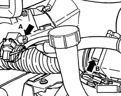
15. On vehicles built before 12/92 or 5/93: adjust idle speed if necessary (screws) and CO content (screw B) alternately turning the adjusting screws. Preliminarily remove the safety plug of the CO adjustment screw (if available). To do this, drill a hole in the cork with a 2.5 mm drill, then screw a 3 mm self-tapping screw into the hole and remove the cork by the screw with pliers. After adjustment, insert a new plug.
16. Connect the coolant temperature sensor connector.
17. Fit and secure the crankcase ventilation hose to the pressure control valve with a clamp.
Attention! If after that the CO content increases, then this is not due to a faulty adjustment, but as a result of oiling from the engine crankcase, due to oil dilution when driving in a busy city mode.
18. After a quick movement between settlements, the fuel content in the oil decreases and the CO content returns to normal. In the short term, it also normalizes after 30 minutes of continuous movement or after changing the oil.
19. Disconnect the gauges with the ignition off.
20. Interrogate and erase the record from memory. As a result of disconnecting the plug from the coolant temperature sensor, a malfunction was recorded in the memory "Faulty sensor or wiring".
Visitor comments