
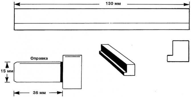
Adjusting ruler and mandrel for checking the camshaft
Usually, the timing is adjusted after a repair in which the toothed belt was removed. If the timing only needs to be checked, then all work steps are carried out without removing the toothed belt.
Removing
1. Remove upper toothed belt guard and cylinder head cover.
2. Mark the direction of movement of the toothed belt with an arrow drawn on it with a felt-tip pen or grease pencil. The direction of rotation of the motor, as viewed from the front, is to the right, clockwise.
3. Set crankshaft to TDC for cylinder 1.
Attention! In doing so, never turn the engine at the central bolt of the camshaft sprocket. crankshaft rotation see subsection 2.5.2.1.
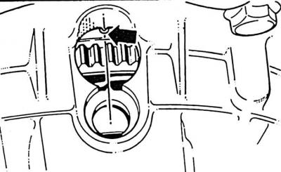 | 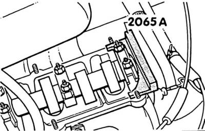 |
4. The crankshaft is in the TDC position for 1 cylinder, if the mark on the flywheel (arrow) match the corresponding mark on the clutch housing (drawing on the left). At the same time, the cam pair of the first cylinder is directed upwards (drawing on the right).
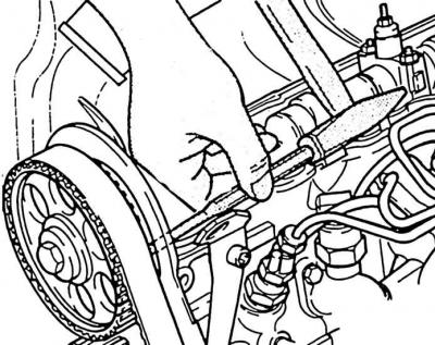
5. In this position, a ruler 2065 A is installed in the camshaft spline. The ruler can also be made independently (see fig. Adjusting ruler and mandrel for checking the camshaft).
6. Install a ruler in the camshaft spline. Setting ruler (VW-N2065A) prevents possible rotation of the camshaft.
7. Balance the setting bar parallel to the cylinder head by turning the crankshaft slightly until one end of the setting bar rests on the cylinder head. Under the other end of the ruler, use a spade feeler gauge to measure the resulting gap. Insert a spade gauge equal to half of the measured gap between the setting ruler and the cylinder head. Rotate the motor until the end of the ruler rests on the probe. Insert a second petal probe of the same size under the other end of the ruler - between the ruler and the cylinder head.
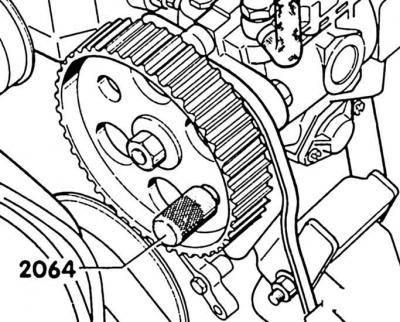
8. Now, mandrel 2064 should enter the hole in the gear of the high pressure fuel pump and the pump bracket. The mandrel jams the injection pump gear. You can make your own frame (see fig. Adjusting ruler and mandrel for checking the camshaft).
9. If the mandrel does not fit into the hole of the high pressure fuel pump bracket, then the timing mechanism must be adjusted again.
10. Loosen the tension roller nut and loosen the toothed belt.
11. Loosen V-belt and remove.
12. Unscrew vibration damper and water pump pulley. To do this, engage first gear, tighten the handbrake, thereby jamming the crankshaft.
13. Remove lower toothed belt cover.
14. Remove toothed belt.
Attention! The toothed belt must be free of tears. A torn belt must be replaced without fail. Breaking the belt during operation can cause severe engine damage.
Attention! If the camshaft must be rotated with the toothed belt removed, no piston must be at TDC. Otherwise, severe damage to the pistons or valves may result.
15. Before rotating the camshaft, all pistons must be set to the same height. To do this, make a mark with chalk at the top of the crankshaft belt pulley (prerequisite: the crankshaft is at TDC for the cylinder), then rotate the crankshaft pulley 1/4 turn (90°) right or left. The chalk mark points to the right or left.
Installation
1. Through the hole in the gearbox, check the alignment of the TDC mark on the flywheel with the corresponding mark.
2. Loosen the camshaft gear bolt 1/2 turn. Knock down the camshaft drive gear by hitting the spike inserted into the 6 mm hole in the rear toothed belt cover with a hammer.
3. Put on the toothed belt.
4. Pull on toothed belt.
5. Tighten the tension roller nut to 45 Nm.
6. Remove the injection pump gear mandrel.
7. Tighten the camshaft drive gear screw to 45 Nm.
Attention! If an old belt is to be used, be sure to observe the direction of travel. Installing the belt in the opposite direction of its movement can lead to a broken belt and engine damage. Therefore, always install the belt so that the marked arrow indicates the direction of rotation of the engine (viewed from the front, clockwise).
8. Remove setting line.
9. Rotate crankshaft 2 turns in direction of engine rotation. Hit the toothed belt between the camshaft drive gear and the injection pump gear with a rubber mallet and check the required toothed belt tension again, tighten if necessary.
10. Check start of injection pump fuel supply (see subsection 2.17.7.6).
11. Install vibration damper, belt pulley and lower toothed belt guard.
12. Install the cylinder head cover gasket, screw on the cylinder head cover. The nuts are tightened to a torque of 10 Nm.
13. Install the upper toothed belt cover.
Visitor comments