



Checking and adjusting values of piston stroke
| Engine | 1X, DAV | ABL |
| Test value: piston stroke, mm | 0,93 – 1,07 | 0,85 – 0,95 |
| Adjustment value piston stroke, mm | 1,00±0,02 | 0,90±0,02 |
1. Set cylinder 1 to TDC. To do this, turn the crankshaft so that the TDC mark on the flywheel and the clutch housing overhang, as well as the mark on the fuel injection pump gear and console, coincide (see subsection 2.5.2).
2. Do not pull out the cold start accelerator control cable.
3. The timing belt tension must be normal.
5-cylinder engine
4. Remove the lower engine compartment splash guard.
5. Fold the radiator forward together with the lock support.
6. Remove the fuel injection pump drive toothed belt cover.
7. Unscrew the threaded plug on the fuel injection pump cover.
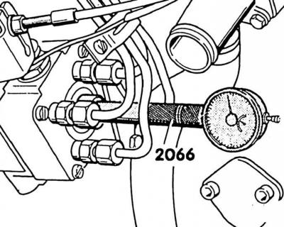
8. Screw in an adapter instead of a plug (V.A.G-2066) with a small watch micrometer (measuring range 0–3.0 mm) until the micrometer pointer starts to move. Set the micrometer by the adjusting ring to "0". Then press the micrometer further: the reading on the scale is approximately 2.5 mm (5-cylinder engine: 2.0 mm).
9. Turn the crankshaft gradually in the direction opposite to the engine rotation (counterclockwise) until the micrometer needle stops moving.
10. Set the micrometer with a reading of about 1 mm to "0". 11. Turn the crankshaft in the direction of engine rotation (clockwise) until the TDC mark on the flywheel coincides with the corresponding mark. The micrometer should now show the test value (see table. Piston stroke test and adjustment values).
Attention! If the test pressure is within the permissible limits, then no new adjustment is required. If a new adjustment is to be made, then the adjustment value must be set.
12. To adjust, unscrew the three bolts (2) on the console and the mounting bolt (1) of the rear stop.
13. By rotating the high-pressure fuel pump, set the piston stroke adjustment value and tighten the mounting bolt to a torque of 25 N·m.
14. Remove the micrometer and screw the threaded plug into the pump cover.
Caution! Always replace the sealing ring of the threaded cover. Tightening torque: 15 Nm. In case of depressurization, tightening with a torque of no more than 25 Nm is permitted.
Adjustment
Adjustment of 4-cylinder engine
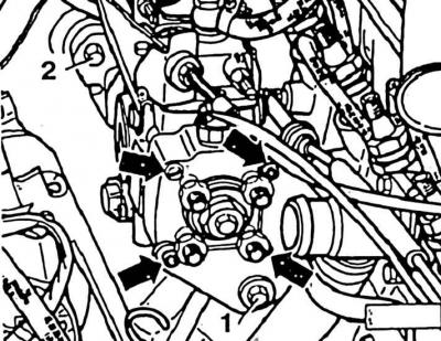
1. Bolts on the console; 2. Rear stop mounting bolts
Adjustment of 5-cylinder engine
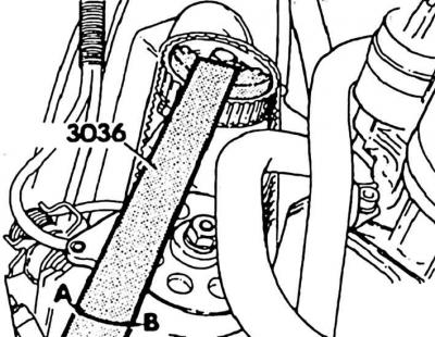
The adjustment can be made as follows:
- by rotating the injection pump after unscrewing the mounting bolts of the console and the 4-cylinder engine stop (first way);
- rotation of the fuel injection pump drive gear (second way).
Attention! In order to be able to observe the micrometer readings when the fuel injection pump drive wheel rotates, the rotation should be performed from below the machine, installed on trestles or a lift.
The first way
1. Holding the fuel injection pump drive gear with a counterstop, loosen the bolt by 1 turn.
2. Check the position of the crankshaft at TDC, if necessary, set it to TDC.
3. Turn the fuel injection pump drive gear with a counter-stop, against the direction of engine rotation (in the direction of arrow A), until the micrometer needle stops moving.
4. Set the micrometer to "0".
5. Turn the fuel injection pump drive gear with a counterstop in the direction of engine rotation (in the direction of arrow B), until the micrometer shows the adjustment value (start of filing).
6. Hold the drive gear in this position with a counterstop and tighten the mounting bolt first to a torque of approximately 50 Nm.
7. Check the start of feed again by rotating the crankshaft back and forth. Then check the start of feed again.
Caution! Due to the slippage of the toothed belt, the test value deviates slightly from the adjusted value.
Example:
| Adjusted value (required value) | = 1.00 mm piston stroke |
| Test value | = 0.93 mm piston stroke |
| Deviation (1.00 minus 0.93) | = 0.07 mm piston stroke |
| Deviation The required value gives the control value in advance (for the second adjustment) | = 1.07 mm piston stroke |
The second way
1. Holding the fuel injection pump drive gear with a counterstop, loosen the bolt by 1 turn.
2. Check the position of the crankshaft at TDC, if necessary, set it to TDC.
3. Turn the fuel injection pump drive gear with a counter-stop against the direction of engine rotation (in the direction of arrow A), until the micrometer needle stops moving.
4. Set the micrometer to "0".
5. Turn the fuel injection pump drive gear with a counterstop in the direction of engine rotation (in the direction of arrow B), until the micrometer shows the adjustment value (in the example given – 1.07 mm).
6. While holding the fuel injection pump drive gear in this position with a counterstop, pre-tighten the mounting bolt to a torque of approximately 50 Nm.
7. Check the start of feed again by rotating the crankshaft back and forth.
Caution: If necessary, repeat the adjustment as many times as necessary until the desired value is reached.
8. Hold the fuel injection pump drive gear with a counterstop and tighten it to a torque of 100 Nm.
9. Remove the micrometer and tighten the threaded plug on the pump cover.
Caution! Always replace the sealing ring of the threaded plug. Tightening torque: 25 Nm.
10. Install the timing belt cover with the lock support and the lower engine compartment splash guard.
Visitor comments