



Verification condition
The engine must be removed.
Work execution procedure
Remove the soundproofing cover and the cylinder head cover of the corresponding cylinder head.
Remove the fuel or tandem pump respectively the GVC. Turn the engine using the counter support - T10172 to the TDC position and remove the torsional vibration damper.
Install the crankshaft locking tool T10195.
Mount the dial indicator from the VAS 6341 set with the VW 387 universal stand and create a pre-tension of about 1 mm on the disc spring of the pump injector as shown (fig. 2.288).
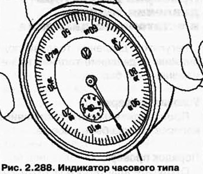
Remove the crankshaft lock pin T10195 and turn the engine against the operating direction of rotation until the indicator arrow stops moving.
Set the dial indicator to "0".
Rotate the engine in the normal direction of rotation to TDC and re-insert the crankshaft locking pin.
The original information is posted on the website (www.VWMANUAL.ru)
Read the measured value on the indicator.
Given values:
- AYH, BKW engines: 5.18 mm ±0.1 mm.
- BLE, BWE motors: 4.95 mm ±0.1 mm.
If the nominal value is reached, assemble the engine.
If the specified pressure value is not achieved, remove the outer cover of support A, install the clamping device T10199 on the camshaft gear and tighten the device bolts to a torque of 40 Nm.
Loosen the camshaft gear mounting bolt with the T10198 head.
Rotate the camshaft with the T10336 head until the specified value is reached.
Tighten the camshaft gear fastening to 150 Nm and repeat the measurement.
If the specified value is obtained, tighten the camshaft gear mount by 90°.
Install the cylinder head cover and soundproof cover.
NOTE: Always replace seals and O-rings.
Visitor comments