
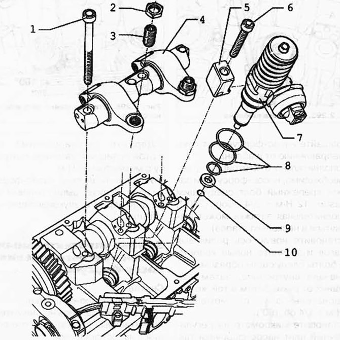
Pic. 2.289. Injector unit components:
1 - bolt 20 Nm + tighten 1/4 turn. (90°); 2 - locknut, 30 Nm; 3 - adjusting screw; 4 - axis of roller levers; 5 - spacer; 6 - bolt 12 Nm + tighten 3/4 turn. (270°); 7 - pump nozzle; 8 - O-ring; 9 - heat-insulating seal; 10 - retaining ring.
Removing
Remove the soundproof cover and cylinder head cover of the corresponding block head.
Rotate the crankshaft until the pair of cams of respectively installed or removed unit injectors point evenly upwards.
Loosen the locknuts of the adjusting screws 1 and unscrew the adjusting screws until the corresponding rocker arm rests on the pusher spring of the unit injector.
Unscrew the fixing bolts 2 axles of the roller levers from external to internal using the end nozzle 3410 and remove the valve actuator roller lever (pic. 2.291).
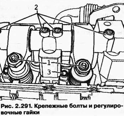
Unscrew the fixing bolt 3 of the spacer using the end nozzle T10054 and remove the spacer.
Disconnect the pump injector plug with a screwdriver. Hold the back of the plug lightly with your finger to avoid distortion.
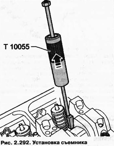
Install the T10055 puller in place of the spacer in the side groove of the unit injector (pic. 2.292).
Carefully tap the unit injector upwards out of its seat on the cylinder head.
Installation
NOTE: When installing a new unit injector, the appropriate rocker arm adjusting screw must be replaced.
During any work related to the adjustment of the unit injector, it is necessary to replace the adjusting screw in the rocker arm and the ball head screw of the unit injector.
New unit injectors are supplied complete with o-rings and heat seal.
When installing an old unit injector, the O-rings and the thermal insulation seal must be replaced.
Before installing the unit injector, check that the three O-rings, the heat seal and the circlip are seated correctly.
NOTE: O-rings must not be twisted.
Lubricate the O-rings and very carefully install the unit injector into its seat on the cylinder head.
Pressing evenly, insert the unit injector into the socket on the cylinder head as far as it will go.
Install the spacer in the side groove of the unit injector.
NOTE: If the unit injector is not at right angles to the spacer, the mounting bolt may come loose, resulting in damage to the unit injector or cylinder head.
Install the pump injector as follows.
Screw the mounting bolts into the spacer until the unit injector can be rotated easily.
Install template T10210 between main bearing seat and injector (pic. 2.293).
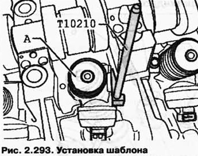
Rotate the pump injector by hand in the direction away from the template.
If necessary, further center the unit injector and tighten the fixing bolt as follows: 12 Nm + 3/4 rev. (270°) (additional tightening can be carried out in several stages).
Install the new roller arm axle and tighten the new mounting bolts as follows.
First internal, then both external by hand. Then, in the same sequence with a torque of 20 Nm + 1/4 rev. (90°).
Establish a micrometer on the adjusting screw of the pump-injector as it is shown in drawing 2.294.
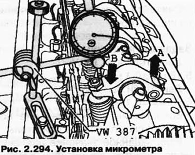
Rotate the crankshaft in the direction of engine rotation until the rocker arm roller is at its highest point.
The side of the roller, arrow A, is at the highest point.
The micrometer, arrow B, is at its lowest point.
Remove the micrometer.
Now tighten the adjusting screw, compressing the spring of the unit injector, until a noticeable resistance is felt (pump injector screwed up to the stop).
Loosen the adjusting screw from the position «twisted up to the stop» 180° (pic. 2.295).
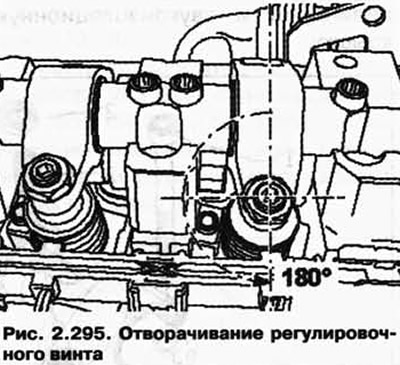
Hold the adjusting screw in this position and tighten the lock nut to 30 Nm.
Install the plug for the unit injector and install the cylinder head cover and soundproof cover.
Visitor comments