
Before starting work on removing the water pump, pay attention to the following recommendations:
- if the car has a radio, then before disconnecting the AB terminals, make sure that you have its security code with you;
- disconnect the battery not earlier than 20 seconds after turning off the ignition. This ensures that the so-called «hot wire» in the air flow meter has ceased to function;
- The battery should only be disconnected when the ignition is off in order to avoid damage to the ignition and injection computer;
- When replacing the water pump, it may also be necessary to replace the coolant if it has been in the system for a long time.
Remove the water pump of the VR6 engine in the following order:
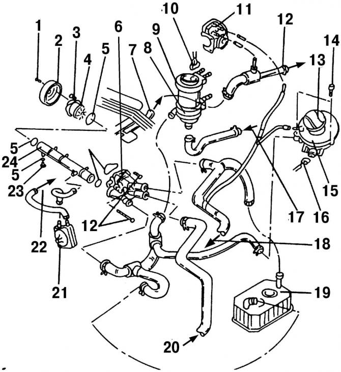
Pic. 190. Location of the remaining parts of the VR6 engine cooling system: 1 - bolt, 25 Nm; 2 - water pump pulley; 3 - bolt, 20 Nm; 4 - water pump; 5 - O-ring, always a replacement; 6 - thermostat housing; 7 - from the cylinder head; 8 - engine cooling pump after it stops; 9 - rubber holder; 10 - plug block of the engine cooling pump after it stops; 11 - throttle body; 12 - to the heat exchanger; 13 - cover; 14 - bolt, 10 Nm; 15 - expansion tank; 16 - plug, black; 17 - from the heat exchanger; 18 - upper coolant hose; 19 - radiator for automatic transmission (if installed); 20 - lower coolant hose; 21 - oil cooler; 22 - to the cylinder block; 23 - threaded drain plug, 10 Nm; 24 - coolant pipeline
- unscrewing the drain plug 23 (pic. 190) in the pipeline 24 of the cooling system running along the engine, drain the coolant. Then immediately screw in the drain plug;
- Disconnect the exhaust pipe from the catalytic converter. Nuts can be discarded immediately as they need to be replaced with new ones;
- disconnect the fuel hose from the cylinder head;
- Remove the HV wires from the spark plugs and remove the HV wire guide from the ignition coil side and pipe side. Turn away bolts of fastening of the central cover and remove it;
- completely remove the air filter housing;
- remove the air flow meter;
Note. If the battery terminals have not yet been removed, then check that the ignition has been turned off at least 20 seconds ago.
- remove the V-belt;
- remove the vacuum hose from the fuel pressure regulator (intake manifold top);
- disconnect the vacuum hose leading to the brake booster located at the top of the intake manifold;
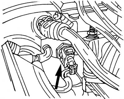
Pic. 191. An arrangement of a plug block of the gauge of temperature of a cooling liquid (shown by arrow)
- disconnect the plug (pic. 191) coolant temperature sensor and unscrew the sensor from the top of the intake manifold;
- fasten the engine to the appropriate hinges and use a hoist to slightly raise the engine in such a way as to unload its suspension;
- remove the right front engine mount;
- slowly lower the right side of the engine (drive unit) until the water pump pulley is accessible. At the same time, make sure that no connections, pipelines, wires, hoses, etc. are stretched;
- fix the water pump pulley in a fixed position, unscrew the mounting bolts and remove the pulley;
- unscrew the mounting bolts and remove the water pump. To remove the pump, move the motor slightly to the left to make room and remove the pump. The sealing ring is still on the pump and must be replaced with a new one.
Note. Check pump after removal for oil leaks (which are most often marked with rust) and rotate the hub to assess the condition of the bearing.
Install the water pump in the reverse order of removal, following these recommendations:
- tighten the pump mounting bolts to a torque of 20 Nm, and the pulley mounting bolts to a torque of 25 Nm;
- put on the drive belt and adjust its tension (see subsection 5.7).
Visitor comments