



Contents: Checking the axial clearance ↓ Valve sizes ↓ Table 6.4 a. Dimensions of valves of…↓ Table 6.4 b. Engine 1Y valve…↓ Identification of camshafts ↓ Valve timing with 1 mm valve lift ↓
The elements of the gas distribution mechanism are shown in Fig. 6.25.
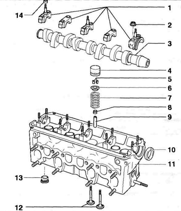
Fig. 6.25. Elements of the gas distribution mechanism:
1 - Camshaft main caps; 2 - Nut; 3 - Camshaft; 4 - Hydraulic compensator; 5 - Rusks; 6 - Upper spring plate; 7 - Valve spring; 8 - Valve stem seal; 9 - Valve guide bushing; 10 - Camshaft oil seal; 11 - Cylinder head; 12 - Valves; 13 - Vortex chamber (only on engine 1Y); 14 - Lower conical seal.
Checking the axial clearance
Checking the axial clearance of the camshaft using an indicator is shown in Fig. 6.26.
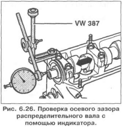
Permissible axial clearance: 0.15 mm.
VW 387 - Indicator bracket.
Valve sizes
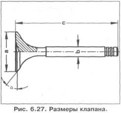
The valve dimensions are shown in Fig. 6.27.
(The text is copied from this portal www.vwmanual.ru)
The dimensions of the valves of the AEY, AFN, ANV, AHU, AKW, ALE engines are given in Table 6.4 a, and those of the 1Y engine are given in Table 6.4 b.
Table 6.4 a. Dimensions of valves of engines AEY, AFN, AHB, AHU, AKW, ALE
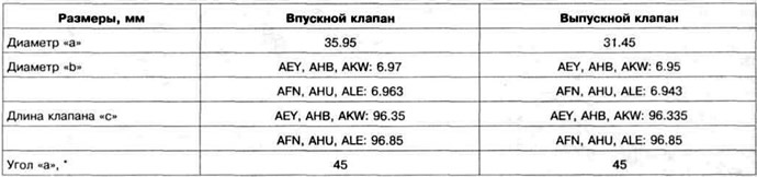
Table 6.4 b. Engine 1Y valve dimensions

Identification of camshafts
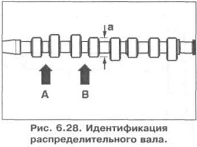
Main cam diameter: 38mm.
The camshaft identification is stamped between the intake and exhaust cams.

Identification of the camshaft is shown in Fig. 6.28.
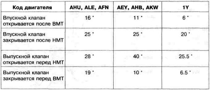
Valve timing with 1 mm valve lift
Visitor comments