
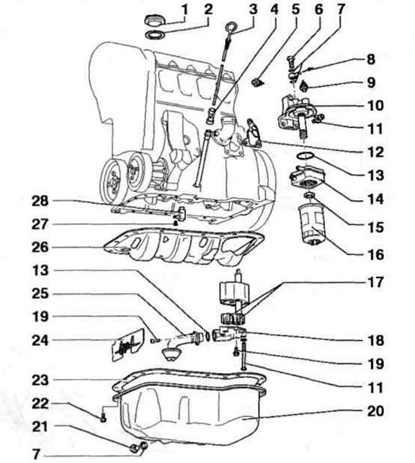
Pic. 6.36. Elements of the lubrication system:
1 - Cover: 2, 12, 23 - Gaskets; 3 - Oil level indicator; 4 - Guide sleeve; 5 - Oil pressure sensor (0.25 bar, blue); 6, 11, 19, 22, 27 - Bolts; 7 - Oil seals; 8 - Oil pressure sensor (0.9 bar, brown); 10 - Oil filter bracket; 13 - O-ring; 14 - Oil cooler; 15 - Nut; 16 - Oil filter; 17 - Oil pump gears; 18 - Oil pump cover with bypass valve (5.7-6.7 bar); 20 - Pallet; 21 - Drain plug; 24, 26 - Oil deflectors; 25 - Oil intake; 28 - Oil can.
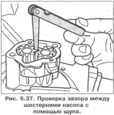
Checking the clearance between the pump gears with a feeler gauge is shown in fig. 6.37. Clearance of the new pump: 0.05 mm. allowable wear: 0.20 mm.
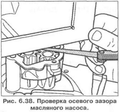
Checking the axial clearance of the oil pump is shown in fig. 6.38. Permissible wear: 0.15 mm.
Visitor comments