
The control element of the transfer case E473, with the ignition off, is turned to the position «LOW».
Transfer case control element E473 is in position «LOW».
Shaft with interrupted gear sector 1 must be in position A.
a = ok. 10° (pic. 3.125).
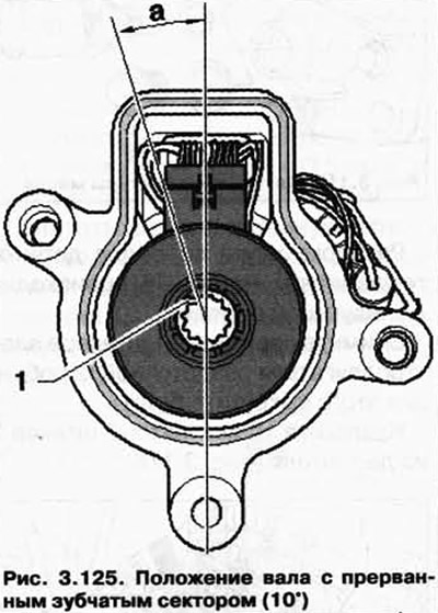
If necessary, put the shaft with a broken row of teeth 1 on the transfer box electric motor as shown in Figure 3.125 (e.g. with a screwdriver).
The control element of the transfer case - E473 - is not in position «LOW».
Shaft with interrupted gear sector 1 must be in position A.
a = ok. 60° (pic. 3.126).
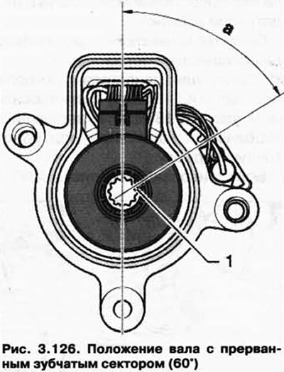
If necessary, put the shaft with a broken row of teeth 1 on the transfer box electric motor as shown in Figure 3.126 (e.g. with a screwdriver).
For the transfer case motor, ensure that the O-ring is seated at the base of the transfer case seal groove.
Install the transfer case motor onto the transfer case mounting sleeves 2.
When doing this, make sure that the interrupted row of teeth of the transfer case motor and the shift control shaft/transfer case coincide.
Screw in and tighten the transfer case motor bolts (rice. 3.124).
Install holder D.
Connect plug connections A, B and C (rice. 3.123).
If available, install a shield over the transfer case motor.
Check the transmission oil level in the transfer case.
Torque:
- transfer box electric motor to transfer box - 27 Nm;
- holder to the transfer case - 14 Nm.
Visitor comments