



The transverse lever through the wheel bearing housing is connected to the suspension strut. Since the wheel bearing housing is connected to the suspension strut with bolts, using thinner bolts, it is possible to change the angle within certain limits (and thus wheel alignment) between the shock absorber axle and the wheel bearing hub.
The upper support of the shock absorber strut is located in an appropriately designed cap and is screwed to the body from the side of the engine compartment.
The torque from the engine is transmitted to the wheels through two cardan shafts, each of which has two joints of equal angular velocity. Of the two tie rods, only the right one can be used to adjust the wheel alignment.
A so-called positive running gear can be fitted as special or standard equipment. In this chassis, the shock absorber struts are more rigidly connected to the front axle, and the entire chassis is located lower.
Attention: Welding and straightening work on the bearing and guiding parts of the front wheel suspensions is not allowed. Always replace self-locking nuts in case of repair.
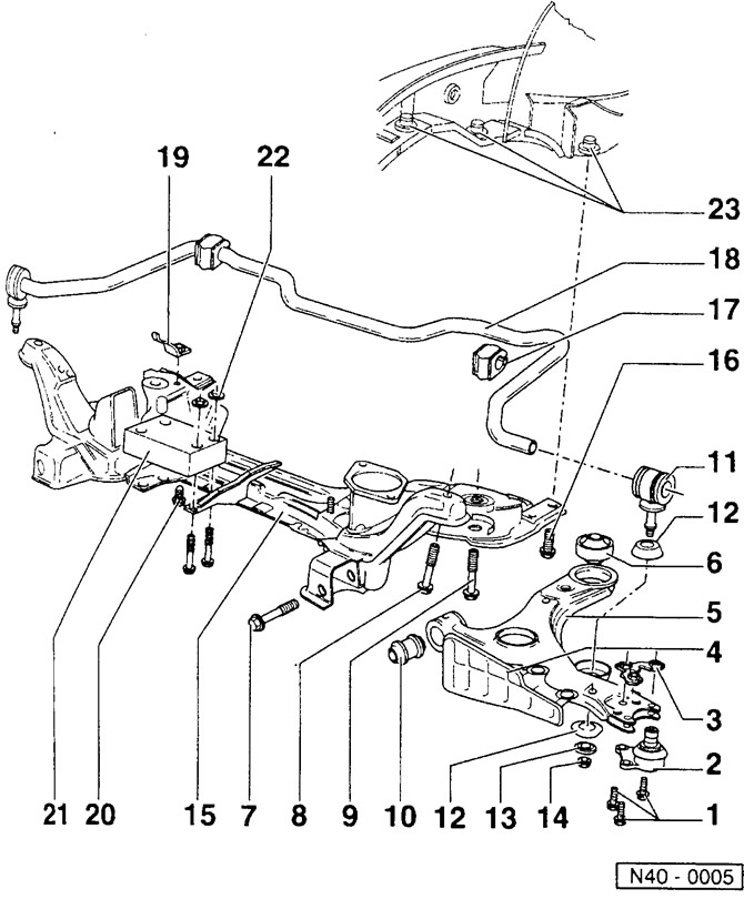
- 1 - bolts, 35 Nm
- 2 - ball joint
Check rubber boot for damage, replace ball joint if necessary.
- 3 - shaped steel plate with nuts
Self-locking, always replace.
- 4 - spoiler (cowl)
Attaches to the transverse arm with clamps.
- 5 - transverse lever
- 6 — the back bearing of the cross-section lever
The kidney-shaped notch faces the middle of the car. One of the applied arrows is facing in the direction of driving into the transverse arm.
- 7 - bolt, M12x1.5x82, 50 Nm + turn by 90°
- 8 - bolt, M 12x1.5x65, 70 Nm + 90°turn
- 9 - bolt, M12x1.5x78, 70 Nm + 90°turn
- 10 - front bearing transverse lever
When installing, use only acid-free lubricant, such as lubricating soap.
- 11 - connecting rod
The tie rod eye points in the direction of travel to the rear.
- 12 - connecting rod bearing
The enlarged diameter faces the transverse arm.
- 13 - washer
The protrusion faces away from the bearing.
- 14 - self-locking nut
- 15 - front axle beam
When removing the engine and gearbox, intercept. Pull the beam together with transverse levers without steering gear downwards using a VAG 1383 gearbox hoist or a garage jack and a wooden spacer. After installation, check the position of the steering wheel and measure the parameters of the vehicle chassis from the front. Align the power unit.
- 16 - bolt, 65 Nm
- 17 - stabilizer bearing
- 18 - stabilizer
- 19 - stabilizer clamp
Pay attention to the different diameters depending on the car model.
- 20 - bolt, 25 Nm
- 21 - shock absorber
Only with 4-cylinder engine. Pay attention to the installation position. Most should be located above the front axle beam.
- 22 - self-locking tie, 25 Nm
- 23 - cap nut
Visitor comments