



2. Raise the front of the vehicle, support it securely on jack stands, and remove both front wheels.
3. Remove the front seats and engine cover.
4. Use a crossbar placed on supports on the driver's cab floor and connected to the engine lifting eyes to support the weight of the engine.
5. Working under the vehicle, disconnect the ends of the radial arms from the body brackets.
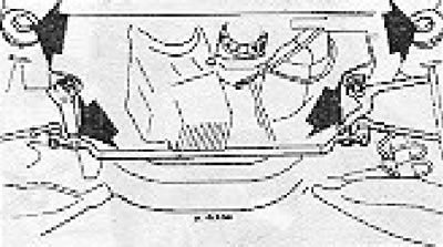
Figure 11.20. Radial arm and rod connections.
6. Disconnect the center section of the steering rod from the steering gear lever. To do this, use a special separator for ball joints.
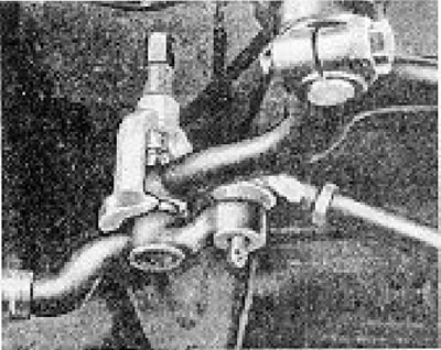
Figure 11.21. Releasing the steering rod ball joint.
7. Unbolt the stabilizer clips from the body, then disconnect the brake line and four-way adapter from the side. Quickly close the end of the brake line to prevent fluid loss.
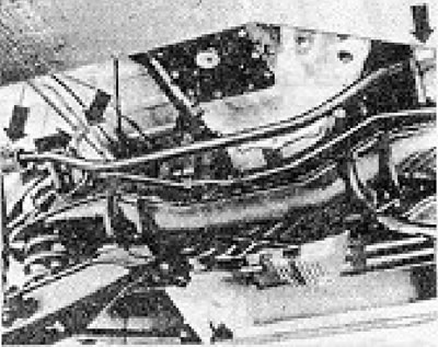
Figure 11.22. Stabilizer clamps and four-way brake line adapter.
8. Loosen and remove the engine mounting nuts, working underneath the engine mounting brackets.
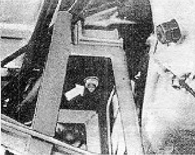
Figure 11.23. Engine mounting nut.
9. Support the weight of the axle crosspiece with a movable jack, then disconnect it from the side parts.
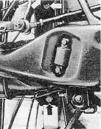
Figure 11.24. Bolts for fastening the crosspiece to the side parts.
10. Slowly lower the jack and, with the help of at least one assistant, remove the entire suspension assembly from the vehicle.
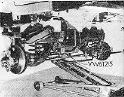
Figure 11.25. Removing independent suspension.
11. Installation is carried out by performing the above steps in reverse order. Tighten all nuts and bolts to the required torque and adjust the length of the radial arms as described in Section 6.
12. Bleed the brake system as described in Chapter 9.
Visitor comments