



2. Remove the disc/hub assembly and bearings as described in Section 4.
3. Remove the nut from the ball joint tie rod end taper pin, then disconnect it from the tie rod at the hub carrier using a suitable tool.
4. Remove the mounting roller pin.
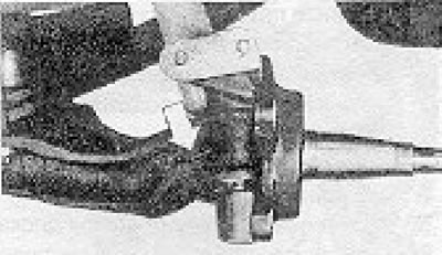
Figure 11.26. Roller pin retaining the main pin.
5. Remove the spring clip from the top of the hub carrier, then the cap with the grease nipple and two O-rings.
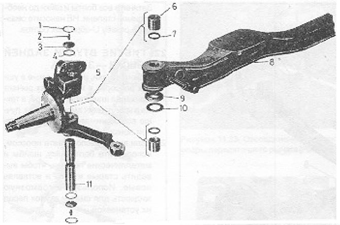
Figure 11.27. Main pin and adjacent parts (LT 40, 45): 1 - Spring clamp; 2 - Grease nipple; 3 - Cap; 4 - O-ring; 5 - Hub carrier; 6 - Bushing; 7 - Gasket; 8 - Bridge; 9 - Thrust bearing; 10 - Washer; 11 - Vowel pin.
6. Using a measuring tool, measure the distance from the top of the hub carrier to the top of the master pin and record it.
7. Remove the main pin in a downward direction. If the bushings are badly worn, the pin may almost fall out, but if this is not the case, you will need a portable press to remove it. Be extremely careful not to damage the bushings unless you intend to replace them.
8. Remove the hub carrier.
9. Installation is carried out by performing the above steps in reverse order. Before installing the main pin (from bottom to top) lubricate it and mark the position of the washer and thrust bearing. The maximum up-and-down clearance between the axle beam and the hub carrier is 2.0 mm. If this clearance is greater, replace the washer with a thicker one, choosing from nine available sizes.
10. Install the master pin in the originally marked position and hub carrier and insert the new roller pin.
11. Install O-rings, caps, nipples and spring clips.
12. Reinstall the disc/hub and adjust the bearings.
13. Connect the steering rod and brake shoe.
14. Inject grease through the nipples.
Visitor comments