



2. Remove the wheels.
3. Remove the disc/hub assembly and bearings as described in Section 4.
4. Disconnect the lower shock absorber mounts.
5. Disconnect the stabilizer arms.
b. Disconnect the ball joints of the tie rod ends from the hub carrier arms.
7. Support the bridge beam with a movable jack and disconnect the springs from it by unscrewing the nuts of the U-bolt.
8. Remove the axle beam from the vehicle.
9. Installation is carried out by performing the above steps in reverse order. Tighten all nuts and bolts to the specified torque and adjust the wheel bearings as described in Section 4. Make sure the steering lock stop is located on the axle surface facing the rear of the vehicle.
(The original can be viewed on the portal: «VWMANUAL»)
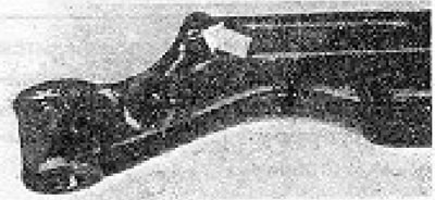
Figure 11.30. Lock stop on the bridge beam (indicated by the arrow).
Visitor comments