



2. The connecting rod has one ball joint, and the other is permanently fixed to the lever.
3. Removal of all ball joints is carried out in the same way. Loosen and remove the nut from the ball joint cone pin, then use a special tool to drive the pin out of the eye.
4. If the ball joint can be disconnected from the control arm, always mark the installation (number of visible thread turns) before removal. In this case, it will be possible to install the new ball joint in the original position.
5. Never apply grease to the taper pin before inserting it into the eye.
6. Sometimes it is impossible to unscrew the cone pin nut because the ball is turning in the socket at the same time. If this situation occurs, place a jack under the ball joint and apply pressure to bring the tapered pin into closer contact with the eye.
7. No matter how careful you are when installing new ball joints in their original position, always check that the front wheels are installed as specified in Section 30 after completion of work.
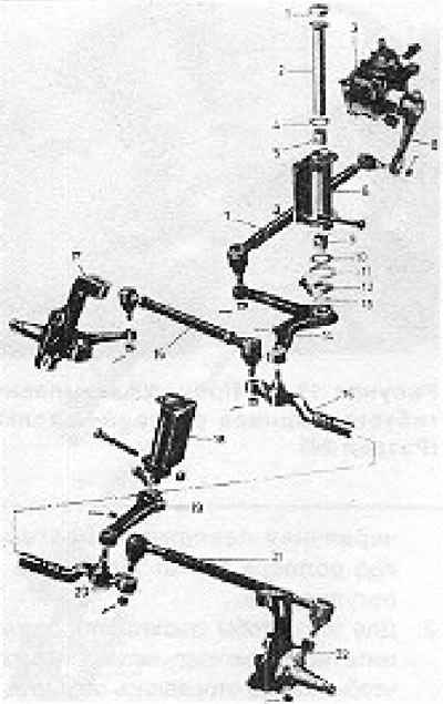
Figure 11.32. Steering mechanism (independent suspension): 1 - Cap; 2 - Idle spindle; 3 - Steering box; 4 - Plate washer; 5 - Bushing; 6 - Roller; 7 - Connecting rod; 8 - Lever; 9 - Bushing; 10 - Special washer; 11 - Gasket; 12 - Support ring; 13 - O-ring; 14 - Knee lever; 15 - Transmission lever (part); 16 - Adjustable tie rod end; 17 - Hub carrier; 18 - Roller; 19 - Roller lever; 20 - Transmission lever (part); 21 - Non-adjustable tie rod end; 22 - Half shaft.
Visitor comments