



2. Disconnect the ball joints of the transmission lever from the shaft arms using a suitable tool.
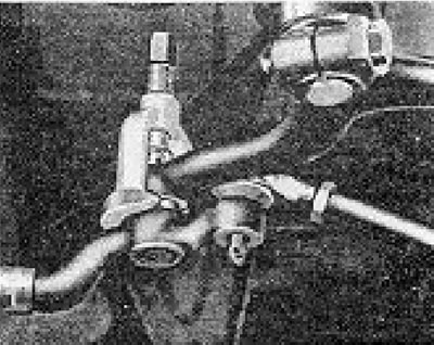
Figure 11.33. Disconnecting the ball joint of the transmission lever (Display 24).
3. Disconnect the ball joint of the connecting rod from the roller lever.
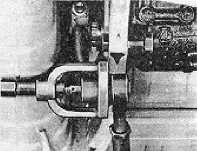
Figure 11.34. Disconnecting the ball joint of the connecting rod (Section 24).
4. Loosen the roller mounting bracket bolts and remove the roller arm assembly from the vehicle.
5. Clamp the bracket in a vice and loosen and remove the through bolt of the roller lever.
6. Remove the roller lever from the spindle.
7. Remove the spindle bushings by tapping them out.
8. Insert the new bushings using a press, or use the bolt, nut and thrust washers to install them in place. Make sure the top bushing is flush with the surface. The lower bushing should protrude between 0.8 and 1.1 mm.
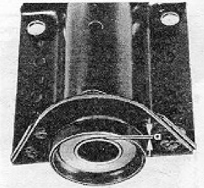
Figure 11.35. Protrusion of the lower roller bushing (Section 24). a = 0.8 to 1.1 mm
9. Installation is carried out by performing the above steps in reverse order. Apply grease to the inside surface of the spindle housing and bushing, and follow the sequence of installing washers and gaskets on the roller arm.
Visitor comments