



2. Lower the wheel and place a jack under the lower control arm to support it.
3. Using the Aplena key, loosen the bolts securing the upper pivot mount to the suspension arm.
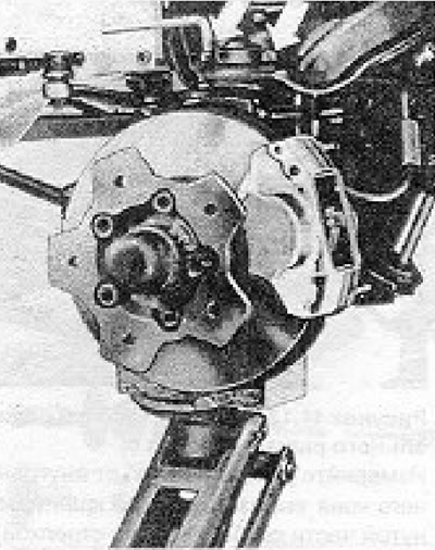
Figure 11.16. Ball joint mounting bolts.
4. Lower the jack under the lever. As the hub carrier moves downward, the upper pivot mount will disengage from the upper control arm.
5. Mark the position of the eccentric washers on each side of the control arm mount in relation to the control arm using quick drying paint or by scratching. This is important for the approximate setting of wheel alignment (see Section 30).
6. Unscrew the nut from the disputed shaft, from the inner end of the upper suspension arm.
7. Remove the support shaft and then the upper control arm.
8. Installation is carried out by performing the above steps in reverse order, but make sure that the end of the support shaft on which the hexagonal protrusion is located is facing the front of the car, and the position of the eccentric washers in relation to the lever is maintained in its original position.
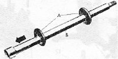
Figure 11.17. Upper bow support pin: A - Eccentric washers; B - Val.
9. It is recommended that after completing the work, the wheel alignment be checked as described in Section 30.
Visitor comments