
English Русский
Български
Беларускі
Український
Српски
Hrvatski
Română
Polski
Slovenský
Magyar
  |  Articles  |  Sitemap  |  Contacts  |    |
Car maintenance Ford Car maintenance Hyundai Car maintenance Chevrolet Car maintenance BMW Car maintenance Audi Car maintenance Opel Car maintenance AvtoVAZ
VWmanual.ru


Main   Passat   Golf   Polo   Touareg   Tiguan   Sharan   Transporter   Others  
LT 28 (1975-1991) LT 2D (1996-2003) Beetle (1960-1986) Caddy 3 (2003-2010)

Disassembly and assembly of the hub with a sliding sleeve of the synchronizer of 1st and 2nd gears (VW Caddy 3)

  • Main
  • Volkswagen
  • Caddy 3
  • Transmission
  • Mechanical gearbox 0AH
  • Disassembly and assembly of the hub with a sliding sleeve of the synchronizer of 1st and 2nd gears
            0


Contents: Installation position of the 1st…↓ 1st gear setting position ↓ Installation position of the 1st…↓
Place the sliding sleeve onto the hub. In this case, the ends (D) of the hub and the recesses for the crackers (E) of the coupling must coincide. After installation, the notch (A) and wide projection (B) must be directed towards the outer splines of the coupling (C).

The device of the hub with a sliding clutch of the synchronizer of 1st and 2nd gears (to figure…

The device of the hub with a sliding clutch of the synchronizer of 1st and 2nd gears (to figure VC4.074):
1. Springs
2. Sliding synchronizer clutch
3. Synchronizer hub
4. Rusks


Insert the crackers into the recesses (arrows). Set the springs at a 120° angle relative to each other. The bent end of the spring should be located in the hollow cracker.
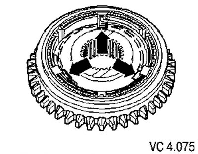
Insert the crackers into the recesses (arrows). Set the springs at a 120° angle relative to each…


Installation position of the 1st gear outer ring


The projections (arrows) point towards the reverse gear.
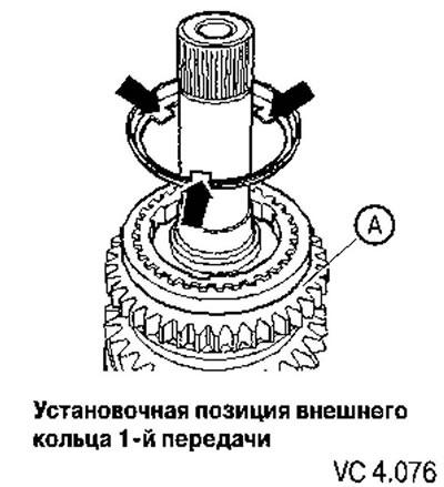
The projections (arrows) point towards the reverse gear.


1st gear setting position


The projections (arrows 1) of the 1st gear (A) must enter the recesses (arrows 2) in the locking ring (8).

[The original material is available on the portal: vwmanual.ru]
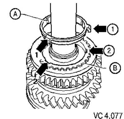
The projections (arrows 1) of the 1st gear (A) must enter the recesses (arrows 2) in the locking…


Installation position of the 1st gear synchronizer clutch


The protrusion (A) is directed towards 2nd gear (B). The cutouts on the protrusion (arrows) should align with the notches on the outer ring.
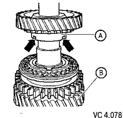
The protrusion (A) is directed towards 2nd gear (B). The cutouts on the protrusion (arrows) should…

This article is available at russian, bulgarian, belarusian, ukrainian, serbian, croatian, romanian, polish, slovak, hungarian
The text has been checked: Kolesnikov Artem

Share information:

Previous articles
Installation position of the outer, inner and locking rings of 2nd gear
Checking the 1st and 2nd gear synchronizer locking ring for wear
Checking the inner ring of the 1st and 2nd gear synchronizer for wear
Setting position of 3rd and 4th gears
Disassembly and assembly of the secondary shaft
Removal and installation the secondary shaft
Next articles
Differential — design description
Removal and assembling the differential


Similar articles from other manuals for VW cars:
Cleaning the water drainage hoses of the sliding roof panel Passat B3 (1988-1993)
Timing belt and timing gears Golf 2 (1984-1993, petrol)
Sliding roof panel: cleaning/lubricating the guide rails Polo 4 (2001-2009)
Sliding door device Transporter T4 (1990-2003)
Link to this page in different formats


Visitor comments


No comments yet


How much will 50 + 20 =


Caddy 3 
  • General information
  • User manual
  • Daily care
  • Maintenance
  • Petrol engines 1.4 l
  • Engine repair
  • Cooling and lubrication system
  • Power and exhaust system
  • Petrol engines 1.6 l
  • Engine repair
  • Cooling and lubrication system
  • Power and exhaust system
  • Diesel engines
  • Engine repair
  • Cooling and lubrication system
  • Power and exhaust system
  • Transmission
  • Mechanical gearbox 0AH
  • Mechanical gearbox 0A4
  • Drive shafts
  • Chassis
  • Car suspension
  • Steering
  • Brake system
  • Body and wiring diagrams
  • Interior and exterior
  • Electrical circuits
Beetle 
  • General information
  • Maintenance
  • Power unit
  • Engine repair
  • Cooling and lubrication system
  • Supply system
  • Exhaust system
  • Transmission
  • Clutch
  • Car gearbox
  • Chassis
  • Front suspension
  • Rear suspension
  • Steering
  • Brake system
  • Wheels and tires
  • Body
  • Exterior
  • Electrical equipment
  • Equipment and devices
  • Power devices
  • Electrical circuits
LT 2D 
  • General information
  • User manual
  • Maintenance
  • Power unit
  • Petrol engines 2.3 l
  • Diesel engines 2.5 l
  • Diesel engines 2.8 l
  • Injection system (diesel 2.8 l)
  • Transmission
  • Clutch
  • Manual gearbox
  • Differential
  • Chassis
  • Car suspension
  • Steering system
  • Brake system
  • Body
  • Body elements
  • Heating system
  • Electrical equipment
  • Equipment and devices
  • Electrical circuits
LT 28 
  • General information
  • Maintenance
  • Power unit
  • Petrol engines 2.0L
  • Petrol engines 2.4L
  • Diesel engines
  • Cooling and heating
  • Fuel and exhaust system
  • Ignition system
  • Transmission
  • Clutch
  • Car gearbox
  • Cardan shaft
  • Rear axle
  • Chassis
  • Brake system
  • Car suspension
  • Steering system
  • Body
  • Body elements
  • Doors, locks and windows
  • Electrical equipment
  • Power devices
  • Equipment and devices
  • Electrical circuits
VWmanual.ru © 2016-2026 | Mobile version | News and articles | Sitemap: EN BG BY UA RS HR RO PL SK HU | Write message | Site search
Passat B2 • Passat B3 • Passat B4 • Passat B5 • Passat B6 • Golf 1, diesel • Golf 1, petrol • Golf 2, petrol • Golf 2 • Golf 3 • Golf 4 • Golf 5 • Polo 3 • Polo 4 • Touareg 1 • Tiguan 1 • Sharan 1 • Transporter T3 • Transporter T4 • LT 28 • LT 2D • Beetle • Caddy 3 •
Our website uses cookies to ensure functionality and convenience.