



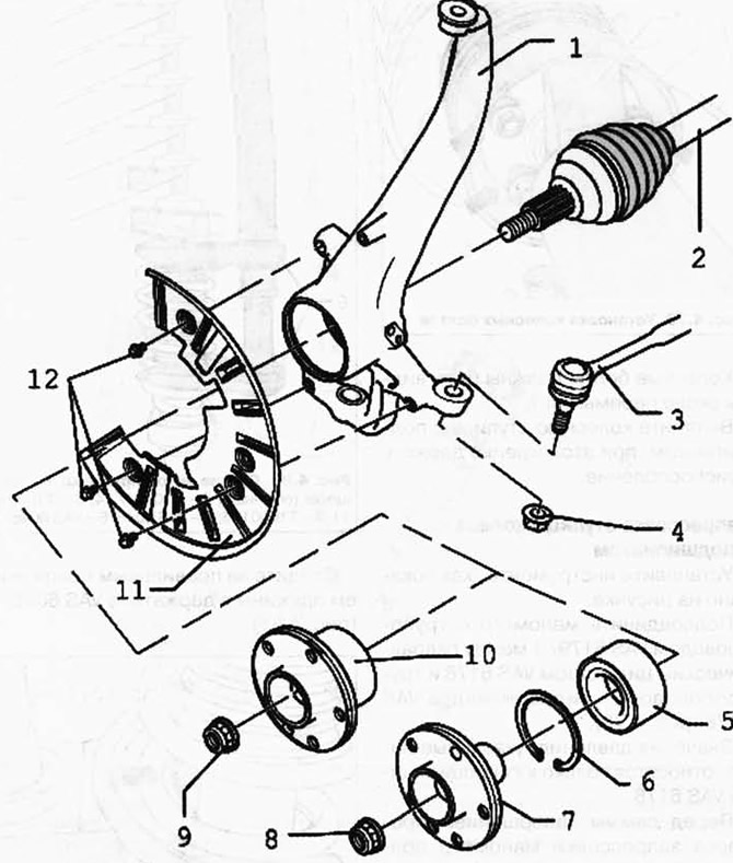
Fig. 4.75. Support components:
1 - wheel hub bearing housing; 2 - drive shaft; 3 - transverse lever; 4 - self-locking nut; 5 - wheel hub bearing; 6 - retaining ring; 7 - wheel hub; 8 - self-locking nut; 9 - self-locking nut; 10 - wheel hub with bearing; 11 - shield; 12 - Hexagon head bolt.
Removal the wheel hub with bearing
First remove the drive shaft. Securely bolt the upper control arm to the wheel bearing housing.
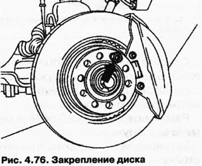
Secure the brake disc with a wheel bolt (Fig. 4.76).
Remove the caliper and hang it on a wire from the body.
Remove the brake disc and shield.
Unclip the speed sensor wire.
Remove the ABS speed sensor.
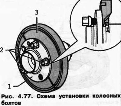
Bolt the T10205/12 clamps to the wheel hub using wheel bolts.
Wheel bolts 2 must not protrude from the rear side of the grips (Fig. 4.77).
The original article is available at VWManual.ru
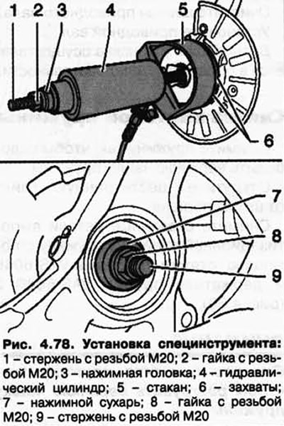
Set up the tools as shown in Figure 4.78.
Install the wheel bolts as shown in Figure 4.79.
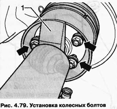
The wheel bolts should be visible near the 1 crossbar.
Pull out the wheel hub with the bearing, holding the tool firmly.
Pressing in a wheel hub with a bearing
Install the tools as shown in the figure.
Connect the pressure gauge with the VAS 6179/1 line between the VAS 6178 hydraulic cylinder and the VAS 6178 hydraulic cylinder line (Fig. 4.78).
The pressure values given below apply only to the VAS 6178 hydraulic cylinder.
Just before the end of the pressing process, the pressure gauge should show a pressure in the range from 90 to 140 bar.
The maximum pressure during pressing must not exceed 310 bar.
Press the wheel hub until it stops.
Clean the drive shaft splines.
Install the drive shaft.
Further installation is carried out in reverse order.
Visitor comments