



Contents: Fixing the subframe ↓ Tightening torques ↓
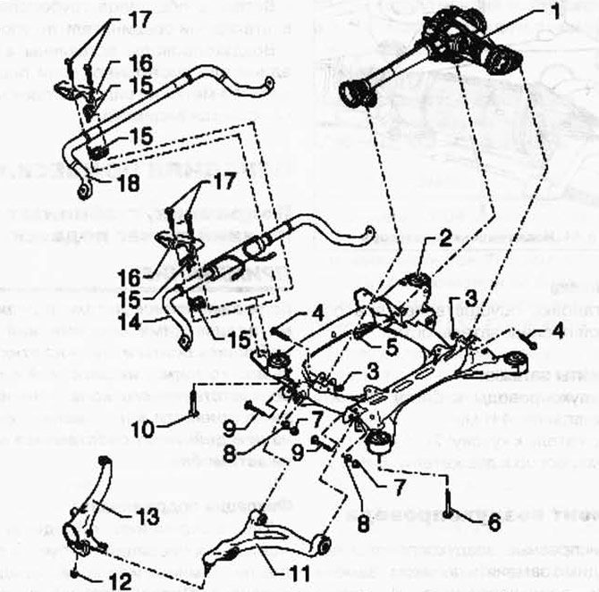
Fig. 4.46. Assembly diagram of the unit - subframe, stabilizer, lower suspension arm:
1 - front main gear; 2 - subframe; 3 - self-locking nut; 4 - Hexagon head bolt; 5 - Hexagon head bolt; 6 - Hexagon head bolt; 7 - self-locking nut; 8 - eccentric washer; 9 - eccentric bolt; 10 - Hexagon head bolt; 11 - lower suspension arm; 12 - self-locking nut; 13 - wheel hub bearing housing; 14 - switchable stabilizer; 15 - stabilizer bearing; 16 - bracket; 17 - Hexagon head bolt; 18 - stabilizer.
NOTE: If parts with rubber-metal bearings have been replaced or the bolts and nuts on these parts have been loosened, the support of the corresponding wheel must be brought to a position where the vehicle's own weight acts on it before tightening them
Fixing the subframe
Certain assembly operations require the removal of the subframe or the entire front suspension. The initial position of the subframe relative to the body can be fixed using the T10300 fixing devices. A prerequisite for using the fixing devices are rubber-metal supports with a round hole for the mounting bolt. When serial production was launched, rubber-metal supports with square holes were installed; the position of the subframe with such supports is not fixed. Always install the fixing devices immediately before lowering the subframe or the entire front suspension. After completing the repair, a test drive must be performed. If the steering wheel is not straight when driving straight ahead, a REVERSE DRIVE must be performed.
Remove the sound insulation under the engine/gearbox
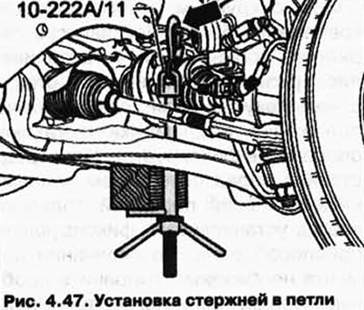
Insert the 10-222 A/11 rods into the engine bracket arrow loops on the right and left sides (Fig. 4.47).
Insert a wooden block A approximately 300 mm long into the brackets of the rods 10-222 A/11 (Fig. 4.48).
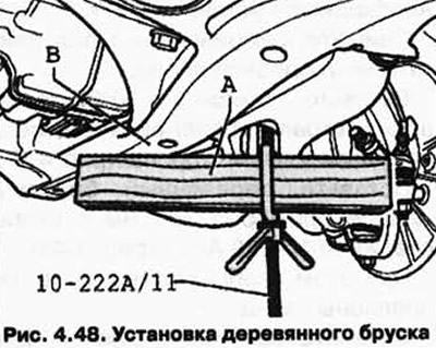
In this case, the staples should be directed backwards.
Tighten the rod clamps so that the wooden blocks rest on the bracket of the mounted units B.
Remove bolts 2 (Fig. 4.49).
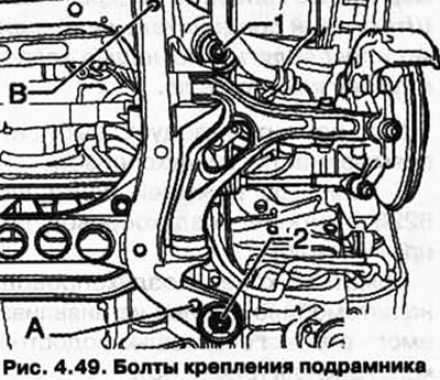
At these two points, "by hand", screw in the T10300 fixing devices up to marking B (Fig. 4.50).
(The original information is posted on the resource: «VWManual.ru»)
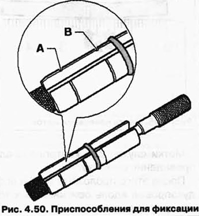
Now tighten the locking devices to a torque of 30 Nm, while holding the sleeve from turning with an open-end wrench.
Now the subframe position is fixed.
Removal of the T10300 fixing devices is carried out in the reverse order.
Tightening torques
Subframe to body: 120 Nm + 180°.
Visitor comments