
Removing
The subframe is removed using a scissor lift table. Install shorter, safety bolts at the front mounting points of the engine mount bracket. The subframe is removed together with. steering gear, front axle drive, lower suspension arms and wheel hub bearing housings. Air springs/suspension struts with support brackets and upper suspension arms remain on the vehicle.
ATTENTION: Switchable stabilizers must be turned on before starting work. Otherwise, unintentional activation of the stabilizers may result in injury.
Turn on the hydraulic system of the switchable stabilizers.
Loosen the wheel bolts.
Raise the vehicle.
Remove the front wheels.
Install the VW 552 spring clamp on both sides of the vehicle in the upper hole in the wheel housing A and on the upper suspension arm B (pic. 4.51).
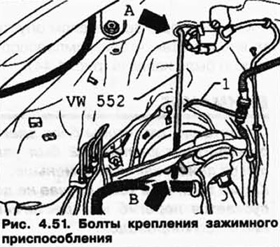
Slightly pinch the lever so as not to damage the ball pin of the suspension joint.
Pull out the top lever (pic. 4.52).

In the wheel arch, disconnect the brake hoses from the brake lines.
Disconnect all electrical wires between body and suspension.
Remove the noise insulation under the engine/gearbox.
Unscrew the hydraulic line holder 1 (pic. 4.53).

Turn off pressure head and drain pipelines 2 from the steering mechanism.
Unscrew the propeller shaft from the front final drive and tie.
Disconnect both hydraulic lines 1 and electrical connection 2 (pic. 4.54).
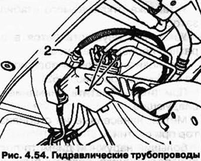
When installing, do not mix up the pipes.
Check if there is a label «in the direction of travel» on the front pipeline. If it doesn't exist, apply a new one.
When unscrewing the pipelines, hold them with an open-end wrench.
Insert rods 10-222 A/11 into the hinges of the engine bracket on the right and left sides (rice. 4.47).
Insert a piece of wood A, approx. 300 mm long, into the brackets of the rods 10-222 A/ 11 (rice. 4.48).
In this case, the brackets should be directed backwards.
Tighten the clamps of the rods, to do this, the wooden blocks must rest on the bracket of mounted units B.
Install the tip of the rolling jack in the engine and gearbox stand VA G 1383 A.
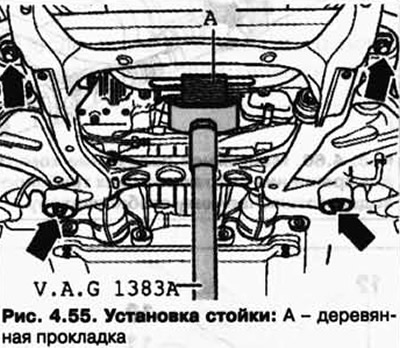
Position the engine and gearbox stand VA G 1383 A under the engine bracket and press lightly (pic. 4.55).
Fix the subframe.
Loosen the subframe bolts.
Unscrew the connecting rod to the left and right of the stabilizer.
Lower the subframe about 50 mm using rods 10-222 A/11.
Use two M14x1.5x90 bolts, such as #104 281 01 bolts, to secure the engine support bracket on the left and right.
Remove the stand for the engine and gearbox VAG 1383 from under the engine bracket.
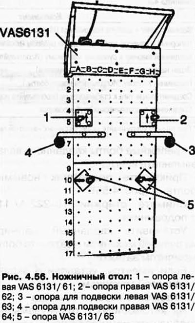
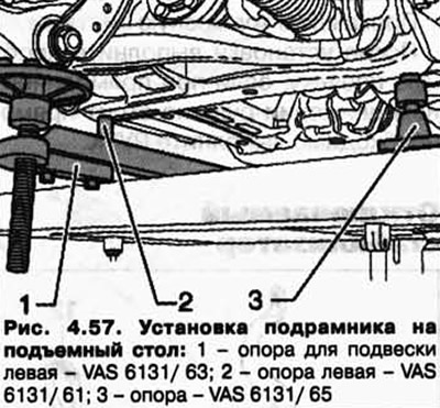
Screw the legs to the scissor lift table as shown (pic. 4.56).
Support the subframe on the lift table (pic. 4.57).
Remove rods 10-222 A/11 from the subframe.
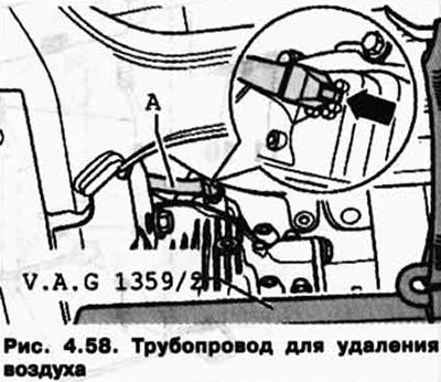
Carefully remove the air bleed line A from the front final drive (pic. 4.58).
Now slowly lower the subframe. Always make sure that this happens smoothly.
Installation
Installation is carried out in the reverse order, paying attention to the following.
Always replace propshaft mounting bolts.
Screw the subframe with new bolts (pic. 4.55).
Remove rods 10-222 A/11 from the subframe.
Install the universal joint on the steering mechanism and tighten the bolt to the torque.
If equipped, install the screen on the steering gear Install the front wheels On vehicles with switchable stabilizers, bleed the stabilizers.
Bleed the brake system. After installation, perform a test drive, if the steering wheel is not straight when driving in a straight line, it is necessary to perform RUUK.
Table 4.8. Tightening torques for threaded connections
| Component | Tightening torque, Nm |
| Upper arm to bearing housing (Use a new nut.) | 95 |
| Pressure and drain pipes on the steering gear | 30 |
| Cardan joint to steering gear (Use a new bolt.) | 40 + 90° |
| Screen on steering gear (if available) | 10 |
| Subframe to body (Use new bolts.) | 120 + 180° |
| Connecting rod to stabilizer (Use a new nut.) | 100 |
| Connection of hydraulic pipelines | 15 |
Visitor comments