
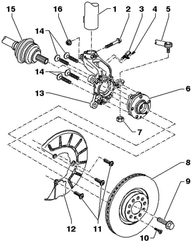
Pic. 4.48. Wheel support components: 1 - shock absorber; 2 - screw with an internal asterisk; 3 - front left wheel speed sensor / front right wheel speed sensor; 4 - screw with an internal hexagon; 5 – a tip of cross steering draft; 6 - wheel hub with bearing; 7 - nut; 8 - ventilated brake disc; 9 – a bolt with a six-sided head; 10 - bolt; 11 - screw with an internal asterisk; 12 - shield; 13 - wheel bearing housing; 14 - screw with an internal asterisk; 15 - drive shaft; 16 - nut
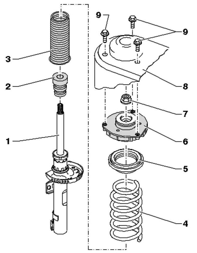
Pic. 4.49. Shock absorber components: 1 - shock absorber; 2 - emphasis; 3 - anther; 4 - helical spring; 5 - thrust ball bearing; 6 – a pillow of an amortization rack; 7 - hex nut; 8 – shock absorber cup; 9 – a bolt with a six-sided head
Removing
Loosen the driveshaft hex bolt.
Remove the wheel.
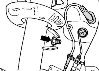
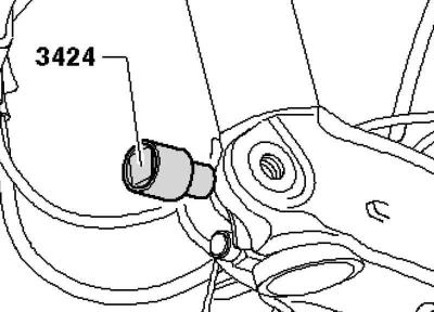
Pic. 4.50. Nut of fastening of connecting draft with an amortization rack
Loosen the hex nut of the suspension strut connecting rod (pic. 4.50).
Loosen the nuts.
Remove the wheel bearing housing with ball joint from the arm.
Pull the driveshaft outer joint out of the wheel hub.
Hang the drive shaft on a wire to the body.
Note: The drive shaft must not hang freely, otherwise the internal joint will be damaged due to the kink.
Reattach the suspension pivot to the arm.
Attach the engine and gearbox stand with support to the hub with a wheel bolt.
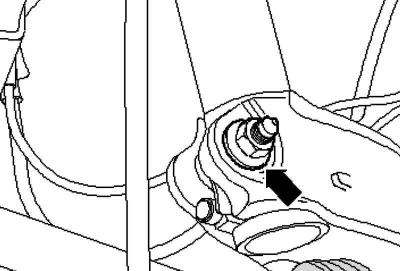
Pic. 4.51. Threaded connection of the wheel bearing housing with the suspension strut
Separate the threaded connection of the wheel bearing housing with the suspension strut (pic. 4.51).
Pic. 4.52. Rectifier installation
Insert the straightener into the spline of the wheel bearing housing (pic. 4.52).
Turn the ratchet 90°and remove from the straightener.
Push the brake disc in the direction of the suspension strut with your hand.
Otherwise, the shock absorber tube may be warped in the bore of the wheel bearing housing.
Remove the wheel bearing housing from the shock absorber tube in a downward direction and lower with an engine and transmission stand until the shock absorber tube hangs freely.
Tie the wheel bearing housing to the console/subframe with wire.
Remove the engine and transmission cradle from under the wheel bearing housing.
Remove the wiper arms.
Remove the plenum box cover.
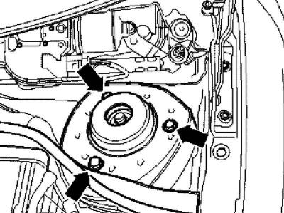
Pic. 4.53. Shock Absorber Upper Mounting Hex Bolts
Remove the shock absorber upper mounting hex bolts and remove the shock absorber (pic. 4.53).
Installation
Attach the engine and gearbox stand with support to the hub with a wheel bolt.
Install the suspension strut onto the wheel bearing housing and secure the strut with the inner sprocket screw and new nut.
The end of the screw with the inner sprocket must point in the direction of travel.
Remove the rectifier.
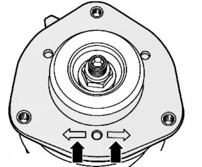
Pic. 4.54. Marking on the spring cushion
One of the two markings on the spring cushion must face in the direction of travel (pic. 4.54).
Remove the wire from the wheel bearing housing.
Carefully lift the wheel bearing housing with the transmission strut until the shock strut cup bolts can be tightened (pic. 4.53).
If necessary, use a ladder, such as a ladder, to tighten the bolts.
Tighten the shock absorber upper mounting hex bolts.
Remove the support.
Tighten the screw connection of the wheel bearing housing with the spring strut (pic. 4.51).
Loosen the nuts.
Insert the drive shaft into the wheel hub.
Insert the wheel bearing housing with the suspension pivot into the arm.
Screw the ball joint to the lever.
Note: Check the boot for damage and twisting.
Note: Install the plenum box trim.
Note: Install wiper arms.
Further installation is carried out in the reverse order.
Install and screw the wheel, tightening torque.
Removing the coil spring
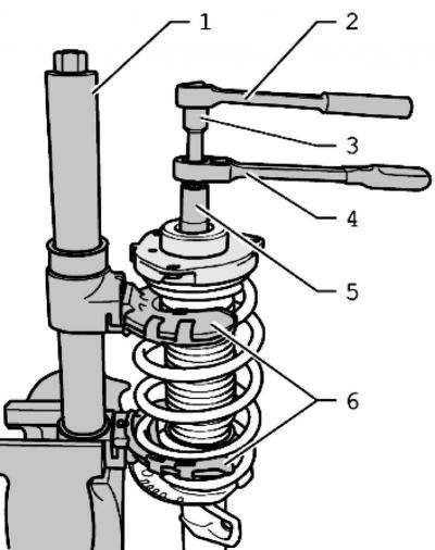
Pic. 4.55. Installing the spring tensioner: 1 – coupler of springs; 2 - torque wrench; 3 - nozzle; 4 - ratchet; 5 - nozzle; 6 - spring holder
Compress the spring with a spring tie until the thrust ball bearing is released.
Caution: First, compress the spring so as to unload the upper spring cup.
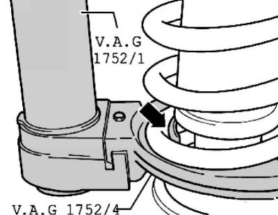
Pic. 4.56. Correct position of the spring in the holder
Ensure the correct position of the spring in the spring holder (pic. 4.56).
Unscrew the hex nut from the piston rod.
Remove the individual suspension strut parts and spring with a spring tie.
Installing the coil spring
Fit the spring with the spring tie onto the lower cup.
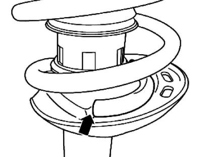
Pic. 4.57. Combination of the end of the coil of the spring and stop
The end of the coil of the spring must be in contact with the stop (pic. 4.57).
On the piston rod, tighten a new hex nut.
Unclench the coupler and remove it from the spring.
Install the shock absorber.
Visitor comments