
Removal and installation of a back axis
Remove wheels.
Remove coil springs.
Disconnect the electrical connectors located between the rear axle assemblies and the body.
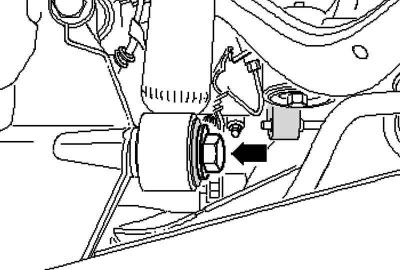
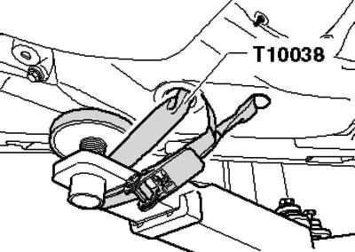
Pic. 4.58. Bolt of fastening of a back rack
Remove the bolt (pic. 4.58).
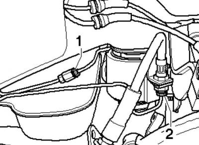
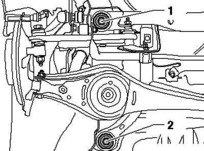
Pic. 4.59. Brake pipe connectors
Disconnect the brake pipes at points 1 and 2 (pic. 4.59).
Disconnect the plug connections for the electromechanical parking brake on the caliper.
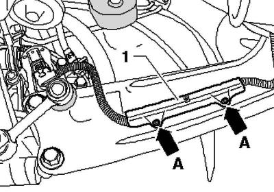
Pic. 4.60. Parking Brake Wire Attachment
Remove fastener 1, to do this, press out the inner rods of the rivets (pic. 4.60).
Remove wire 1 from the support bracket.
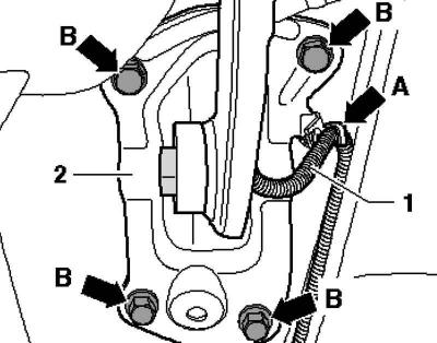
Pic. 4.61. Support bracket fixing
On the body, mark the position of the support bracket 2 (pic. 4.61).
Turn away bolts.
Disconnect the rear left body level sensor connector.
Pic. 4.62. Fixing the car on a lift
Secure the vehicle on both sides of the lift brackets with tension straps (pic. 4.62).
Attention: Otherwise, it may slide off the lift
Install an engine and transmission jack with a universal support for transmission assemblies under the subframe and secure the subframe with a belt.
Pic. 4.63. Subframe mount
Loosen hex bolts 1 or 2 on both sides (pic. 4.63).
Note: For illustration purposes, only the left side of the vehicle is shown in the illustration.
Note: To fix the subframe, it is necessary to screw in the locking devices in turn in positions 1 and 2 on both sides of the vehicle.
Note: Lock the position of the subframe with the latches.
Note: The fasteners must be tightened with a torque not exceeding 20 Nm, otherwise their threads may be damaged.
On both sides, in turn, replace the subframe mounting bolts with clamps and tighten them to 20 Nm.
The position of the subframe is now fixed.
Carefully lower the subframe assembly with the assemblies installed on it.
Note: When lowering, make sure that you have access to the brake lines and electrical cables.
Installing the subframe assembly with the nodes mounted on it
Installation is carried out in the reverse order.
Bleed the brake system
Adjust wheel alignment.
Visitor comments