



Pressing out rubber bushing
Remove the trailing arm.
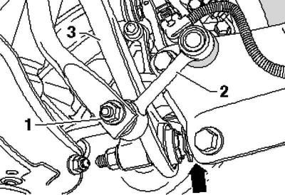
Pic. 4.71. Connecting rod and stabilizer
Clamp the trailing arm in a vise so that support bracket 1 is in contact with the vise (pic. 4.71).
Remove bolt 2.
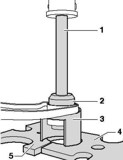
Pic. 4.78. Installing tools: 1 - tube; 2 - mandrel; 3 - tool for pressing out; 4 - pressure plate; 5 - pressure plate
Install the tools as shown in Figure 4.78.
Press out the rubber bushing.
Pressing in rubber-metal bushing
Place the trailing arm on a level surface.
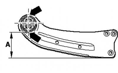
Pic. 4.79. Installation of the trailing arm on the plane
Install the trailing arm on the plane so that the dimension a is 113 mm (pic. 4.79).
Mark a vertical line on the trailing arm bushing.
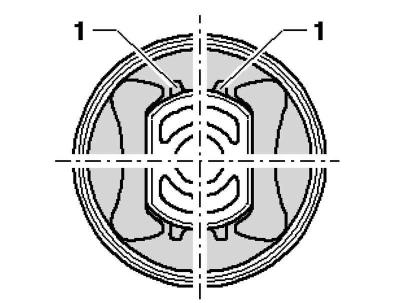
Pic. 4.80. Rubber bushing location
Position the rubber-metal bushing on the trailing arm so that the marked line is between the tabs 1 (pic. 4.80).
Note: Pay attention to the correct mounting position of the rubber-metal bushing relative to the bushing of the trailing arm.
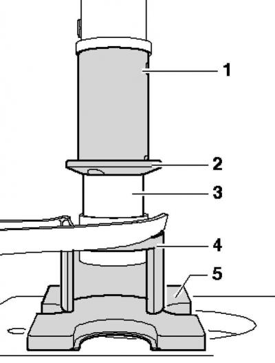
Pic. 4.81. Installing tools: 1 - tube; 2 - pressure plate; the chamfer should be directed to the rubber-metal bushing; 3 - rubber-metal bushing; 4 - tool for pressing out; 5 - pressure plate
Install the tools as shown in the picture (pic. 4.81).
Press the rubber-metal bushing flush.
Install the support bracket to the trailing arm.
Install the trailing arm.
Visitor comments