
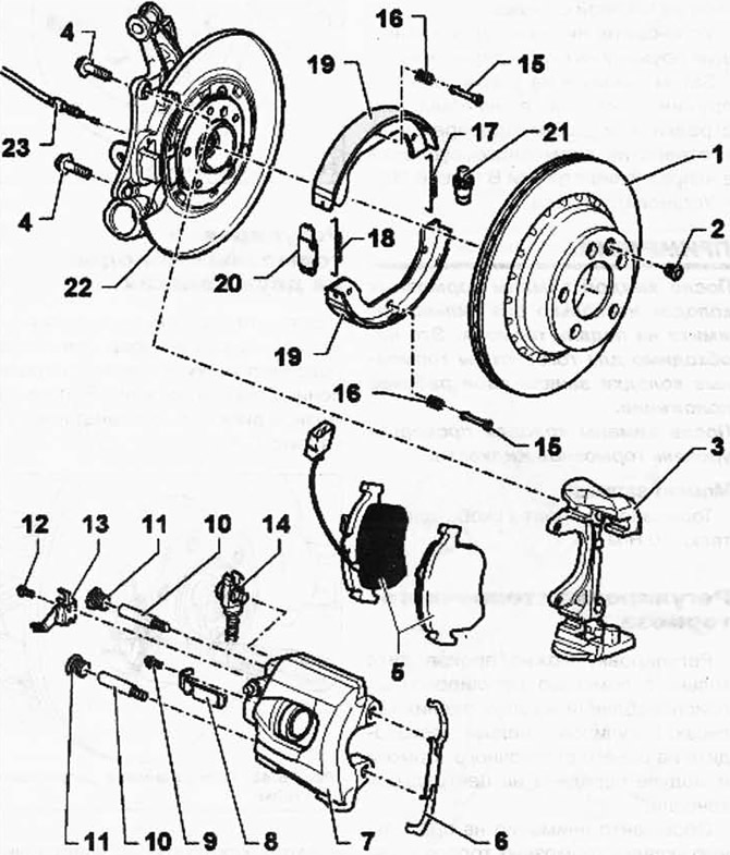
Pic. 6.41. Rear brake components:
1 - brake disc / brake drum; 2 - set bolt, 20 Nm; 3 - bracket-holder; 4 - hex bolt, 200 Nm; 5 - brake pads; 6 - holding spring; 7 - brake caliper; 8 - brake pad wear indicator cable holder; 9 - screw, 10 Nm; 10 - guide bolt, 30 Nm; 11 - cap; 12 - a bolt with an internal hexagon, 8 Nm; 13 - bracket; 14 - brake hose with fitting and hollow screw, 38 Nm; 15 - coupling pin; 16 - pressure spring; 17 - outlet spring; 18 - outlet spring; 19 - brake shoe; 20 - spacer lock; 21 - adjusting nut; 22 - bracket-holder; 23 - rear brake cable.
NOTE: To drain the brake fluid from the reservoir, use the brake system filling and bleeding device VAS 5234 or the brake system filling and bleeding device VAG 1869/4. Before dismantling the brake caliper or disconnecting the brake hose, install the brake pedal stop VAG 1869/2 (at the same time reduce the pressure).
Removing the brake pads
Mark the brake pads if they are to be reused. They must be installed back in their places, otherwise there will be an uneven distribution of braking forces between the wheels.
Remove wheels.
Push the retaining spring in the direction of arrow A until it can be pushed out of the hole in the direction of arrow B (rice. 6.26).
Turn the retaining spring 1 clockwise until it can be removed from the top hole (rice. 6.27).
Disconnect the plug connection 1 of the brake pad wear indicator (pic. 6.42).
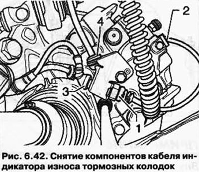
Remove the brake pad indicator cable from holder 2 on the brake caliper.
Remove the lower part of the plug 3 of the brake pad wear indicator and the speed sensor cable 4 from the holder on the brake caliper.
Remove caps (pic. 6.43).
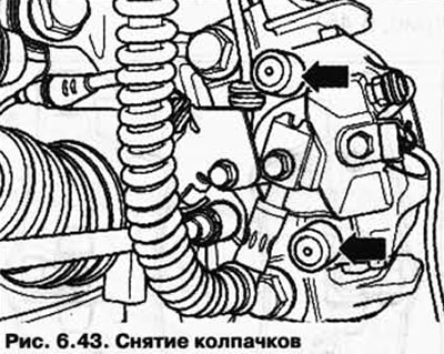
Unscrew and remove both guide pins from the brake caliper.
Remove the brake caliper and secure it with wire so that its weight does not press on the brake hose and damage it.
Remove the brake pads.
Clean the bearing surface of the brake pads in the bracket-holder, remove corrosion.
Cleaning the brake caliper.
Use only alcohol to clean the brake caliper.
Installation of brake pads
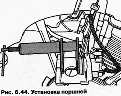
Before pressing the pistons into the cylinder using a special device, it is necessary to pump out the brake fluid from the reservoir. Otherwise, if liquid is topped up, it may leak out and cause damage.
Press in the pistons with tool T10145 (pic. 6.44).
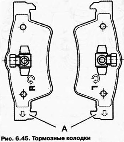
NOTE: Internal brake pads (on the side of the pistons) are installed for a certain direction of movement, so they should be marked.
Brake pads that are installed for a specific direction of movement.
when installed, on the reverse side of the brake shoe must point downwards (in the direction of rotation of the brake disc) (pic. 6.45).
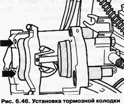
Install the brake shoe with retaining springs into the piston (pic. 6.46).
Install the outer brake shoe into the retaining bracket.
Attach the brake caliper with two guide bolts to the bracket.
Install both caps.
Press the speed sensor cable 4 into the holder on the brake caliper.
Connect plugs 3 and 1 of the brake pad wear indicator in the holder on the brake caliper.
Attach the brake pad wear indicator cable to holder 2 on the brake caliper.
Install the retaining spring in the top hole, then turn clockwise.
Install the lower retaining spring onto the retaining bracket.
Then press the retaining spring first in the direction of arrow A and then at the same time in the hole of the brake caliper in the direction of arrow B (rice. 6.26).
Install wheels.
NOTE: After each replacement of the brake pads, depress the brake pedal firmly several times. This is necessary in order for the brake pads to take their working position. After replacing the pads, check the brake fluid level.
Torque
Brake caliper to caliper: 30 Nm.
Visitor comments