
Work with the VAG 1356 pipe flaring tool on black brake lines is not allowed due to their coating and diameter.
NOTE: Brake pipes may not be bent more than 90°, otherwise they may crack or deform so much that their flow area is critically reduced. The junction of pipelines is best located under the bottom of the car.
NOTE: Connecting fittings should be positioned so that they do not touch moving parts and components. Do not lubricate the lead screw, but only clean with alcohol.
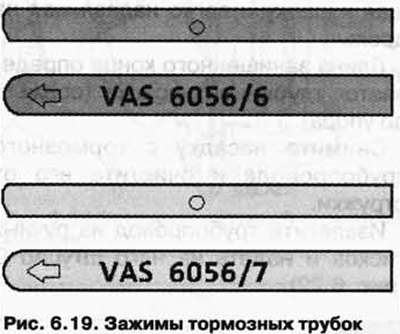
The arrow on the rounded side of the clamps must point towards the edge of the body, and the straight side of the clamps must be installed towards the spindle, otherwise the flare head is not formed correctly (pic. 6.19).
Carrying out work
Unscrew the brake line from the appropriate caliper or wheel brake cylinder. Collect and properly dispose of leaking brake fluid.
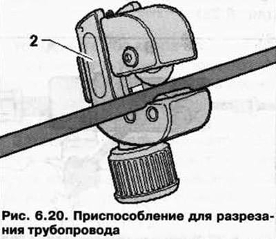
Cut the pipeline in a suitable place (no bends, easy access) with tool 2 (pic. 6.20).
Remove the damaged area.
Remove the sheath at the end of the pipeline.
Clamp the brake pipe in pliers 4 so that approx. 50 mm protrudes from the plastic clamping jaws (pic. 6.21).
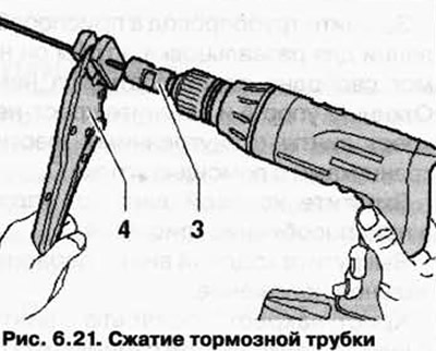
Mount the lining removal tool 3 on the drill and insert the end of the pipeline into the tool.
Cut off the shell by slowly rotating the nozzle and applying light pressure to the drill.
The length of the bare end is determined by the deep end (cut to the brim).
Remove the nozzle from the brake pipe and clean it of chips.
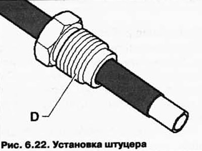
Remove the pipeline from the hand vise and put fitting D on it (pic. 6.22).
Insert the pipe B up to the stop A of the flare tool (pic. 6.23).
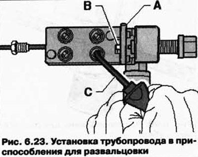
NOTE: When tightening the hexagon socket screws, the brake pipe must rest against the stop, otherwise the pipe will not flare properly.
Clamp the pipeline in the flare tool so that it cannot move freely in it. Swing out stop A and tighten the hexagon socket screws crosswise using angle C.
Screw the lead screw into the fixture until it stops (pic. 6.24).
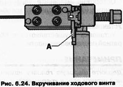
Unscrew the lead screw to its original position.
Loosen the hexagon socket screws in a criss-cross pattern.
Remove the brake pipe from the fixture, clean and check the pipe and flare.
Wash out the brake pipeline established on the car.
Connect the brake filling and bleeding device VAS 5234, put the bleeder hose on the flared end of the pipeline and turn on the brake filling and bleeding device VAS 5234 for a short time so that the brake fluid flushes out the sawdust.
Blow out the pipeline to be installed with compressed air.
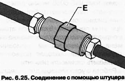
Connect the brake pipes with fitting E (pic. 6.25).
Fix pipelines of brake system.
Bleed the brake system.
Removal and installation of brake pads.
Removing
Mark the brake pads if they are to be reused. They must be installed back in their places, otherwise there will be an uneven distribution of braking forces between the wheels.
Remove wheels.
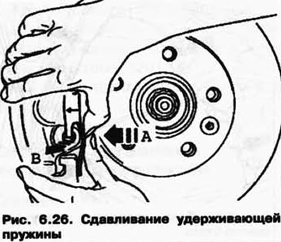
Compress the retaining spring in the direction of arrow A until it can be pressed out of the hole in the direction of arrow B (pic. 6.26).
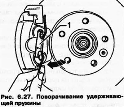
Turn the retaining spring 1 clockwise until it can be removed from the top hole (pic. 6.27).
Disconnect the plug connection 1 for the brake pad wear indicator, remove the cap 2 and remove the cable for the brake pad wear indicator (pic. 6.28).
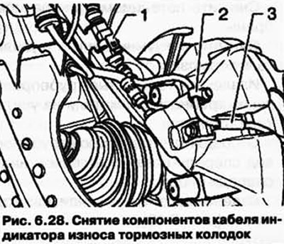
Remove the brake pad indicator cable from holder 3 on the brake caliper.
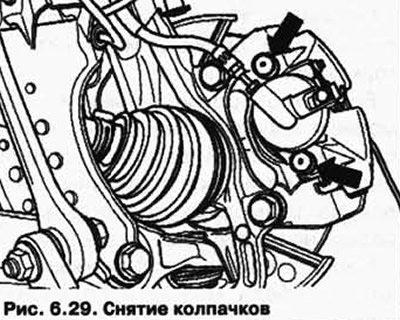
Remove caps (pic. 6.29).
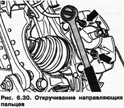
Unscrew and remove both guide pins from the brake caliper (pic. 6.30).
Remove the brake caliper and secure it with wire so that its weight does not press on the brake hose and damage it.
Remove the brake pads.
CAUTION: Do not blow out the brake system with compressed air. This creates harmful dust.
Clean the bearing surface of the brake pads in the bracket-holder, remove corrosion.
Clean the brake caliper (remove glue residue) - The adhesive surface must be dry and clean.
Use only alcohol to clean the brake caliper.
Installation
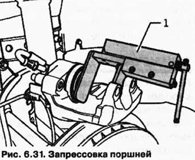
Before pressing the pistons into the cylinder using a special device, it is necessary to pump out the brake fluid from the reservoir. Otherwise, if liquid is topped up, it may leak out and cause damage.
Press in the pistons with tool T10145 1 (pic. 6.31).
NOTE: Internal brake pads (on the side of the pistons) are installed for a certain direction of movement, so they should be marked.
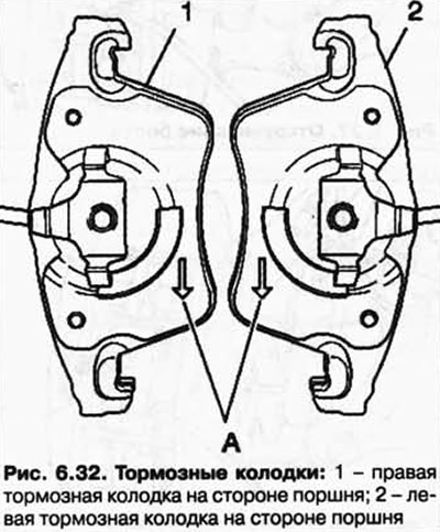
When installed, arrow A on the back of the brake shoe must point downwards (in the direction of rotation of the brake disc).
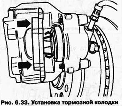
Install the brake shoe with retaining springs into the piston (pic. 6.33).
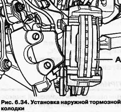
Remove the protective film from the base plate of the outer brake pad.
Install the outer brake shoe A in the retaining bracket (pic. 6.34).
When installing the brake caliper, make sure that the brake pad does not stick to the brake caliper until the correct mounting position is reached.
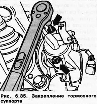
Attach the brake caliper with two guide bolts to the bracket (pic. 6.35).
Install both caps.
Connect plugs 1 of the brake pad wear indicator in the holder on the wheel bearing housing (pic. 6.28).
Attach the brake pad wear indicator cable with cap 2 to the bleeder socket with holder 3 on the brake caliper.
Install the retaining spring in the top hole, then turn clockwise (pic. 6.27).
Install the lower retaining spring onto the retaining bracket.
Then press the retaining spring first in the direction of arrow A and then at the same time in the hole of the brake caliper in the direction of arrow B (pic. 6.26).
Install wheels.
NOTE: After each replacement of the brake pads, depress the brake pedal firmly several times. This is necessary in order for the brake pads to take their working position.
After replacing the pads, check the brake fluid level.
Torque
Brake caliper to caliper: 30 Nm.
Visitor comments