
English Русский
Български
Беларускі
Український
Српски
Hrvatski
Română
Polski
Slovenský
Magyar
  |  Articles  |  Sitemap  |  Contacts  |    |
Car maintenance Ford Car maintenance Hyundai Car maintenance Chevrolet Car maintenance BMW Car maintenance Audi Car maintenance Opel Car maintenance AvtoVAZ
VWmanual.ru


Main   Passat   Golf   Polo   Touareg   Tiguan   Sharan   Transporter   Others  
Passat B2 (1981-1988) Passat B3 (1988-1993) Passat B4 (1988-1996) Passat B5 (1996-2005) Passat B6 (2005-2010)

Removal and installation the camshaft drive belt (VW Passat B2)

  • Main
  • Passat
  • Passat B2
  • Power unit
  • Engines 5-cylinder
  • Removal and installation the camshaft drive belt
            0


Contents: Removal ↓ Installation ↓ Checking and adjusting the tension…↓

Removal


Loosen the generator mounting bolts and, depending on the configuration, the power steering pump mounting bolts.

Remove the alternator drive belt and, depending on the configuration, the power steering pump drive belt.

Remove the crankshaft pulley.

Remove the front timing belt covers.

Disconnect the high voltage wire harness and remove the spark plugs.

Turn the crankshaft to the TDC position of the compression stroke of the piston of the 1st cylinder, aligning the mark on the flywheel with the installation protrusion on the clutch housing and placing the mark on the toothed pulley of the camshaft at the level of the cylinder head gasket.

Slightly loosen the water pump mounting bolts, turn the pump body counterclockwise to loosen the timing belt tension.

Remove the camshaft drive belt

Installation


Note: Do not allow the camshaft to turn when one of the pistons is at TDC.


Set or check the correct position of the camshaft pulley corresponding to the TDC of the compression stroke of the piston of the 1st cylinder: the mark on the pulley should be opposite the upper plane of the camshaft cover gasket.

Make sure that the crankshaft is in the position corresponding to the TDC of the compression stroke of the piston of the 1st cylinder; in this case, the marks on the flywheel and on the clutch housing must match. When adjusting the valve timing mechanism on a removed engine, align the marks on the crankshaft pulley and the upper edge of the oil pump housing.


Place the camshaft drive belt on the pulleys.

Tighten the belt on the pulley teeth.

Tighten the timing belt by moving the water pump housing.

Turn the crankshaft two revolutions and check the position of the timing marks.

Install the front timing belt covers.

Install the alternator drive belt and, depending on the configuration, the power steering pump drive belt and adjust its tension.

Install the spark plugs and high-voltage wire harness.

Check and, if necessary, adjust the ignition timing.

Checking and adjusting the tension of the camshaft drive belt


Turn the crankshaft clockwise to the position corresponding to the TDC of the compression stroke of piston No.1 cylinder.

Remove the upper front camshaft drive belt cover.

Check the tension of the toothed belt by turning it with the force of your thumb and index finger 90 degrees around its axis in the middle of the branch between the camshaft pulley and the water pump. The belt should not turn more than 90 degrees.

To adjust, loosen the water pump mounting bolts, move the pump body using the adjusting lever up for more tension or down for less belt tension.

Tighten the pump mounting bolts.

Turn the crankshaft two revolutions and check the timing belt tension again.

Install the front camshaft timing belt covers.
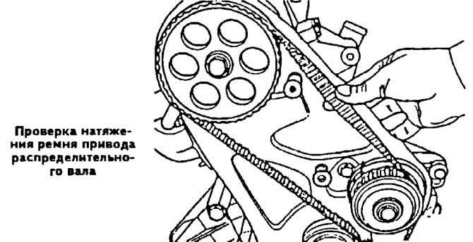
Install the front camshaft timing belt covers.
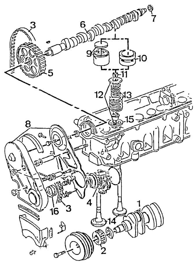

Timing mechanism parts:

Timing mechanism parts:
1 — crankshaft;
2 - toothed pulley of the crankshaft;
3 - toothed belt of camshaft drive;
4 - coolant pump;
5 - toothed pulley of the camshaft;
6 — camshaft;
7 — ignition distributor sensor drive gear;
8 - Front and rear timing belt protective covers;
9 — pusher and valve clearance adjusting washer;
10 - hydraulic pusher;
11 - crackers;
12 — spring support plates;
13 — valve springs;
14 — valves;
15 — oil deflector cap;
16 - guide roller (since 1984 model year).
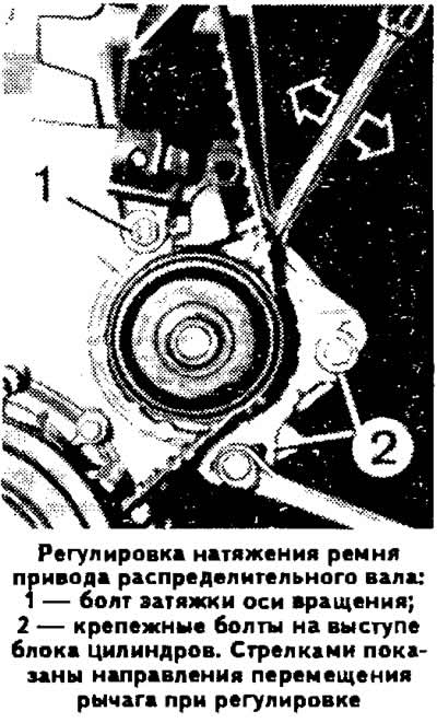

16 - guide roller (since 1984 model year).


The original text is available on the portal VWManual

This article is available at russian, bulgarian, belarusian, ukrainian, serbian, croatian, romanian, polish, slovak, hungarian
The text has been checked: Kolesnikov Artem

Share information:

Previous articles
Removal and installation the ignition distributor sensor
Checking and adjusting the ignition system
The structure and principle of operation of the electronic ignition system
Possible malfunctions of the K-Jetronic fuel injection system, their causes and methods of elimination
Checking and adjusting the K-Jetronic system
Features of the device and the operating principle of the K-Jetronic system
Next articles
Cylinder head
Installing the cylinder head
Disassembly and repair of the cylinder head
Cylinder head assembly
Removal and installation the engine
Disassembling the engine


Similar articles from other manuals for VW cars:
Timing Belt (Camshaft Drive Belt) Golf 1 (1974-1984, petrol)
Timing belt drive with double pulley injection pump Polo 3 (1995-2003)
Checking the belt drive pulleys for misalignment (4.2L petrol… Touareg 1 (2002-2006)
Camshaft drive chain Tiguan 1 (2007-2015)
Removal the toothed drive belt Sharan 1 (1995-2000)
Windscreen wiper drive device Transporter T4 (1990-2003)
Timing belt for camshaft drive LT 2D (1996-2003)
Link to this page in different formats


Visitor comments


No comments yet


How much will 12 + 19 =


Passat B6 
  • General information
  • User manual
  • Maintenance
  • Petrol engine 1.6L
  • Engine repair
  • Cooling and lubrication system
  • Fuel injection system
  • Petrol engine 2.0L
  • Engine repair
  • Lubrication system
  • Cooling system
  • Fuel and exhaust systems
  • Diesel engine 2.0L
  • Engine repair
  • Cooling and lubrication system
  • Fuel and exhaust systems
  • Transmission
  • Clutch
  • Mechanical gearbox
  • Automatic gearbox
  • Drive shafts
  • Chassis
  • Wheels and tires
  • Car suspension
  • Steering
  • Brake system
  • Body
  • Exterior (external elements)
  • Electrical equipment
  • Power devices
  • Lighting and appliances
  • Electrical circuits
Passat B5 
  • General information
  • User manual
  • Weekly checks
  • Maintenance
  • Power unit
  • Engine repair
  • Cooling system
  • Fuel system (petrol)
  • Fuel system (diesel)
  • Engine management
  • Exhaust system
  • Transmission
  • Clutch
  • Car gearbox
  • Drive shafts
  • Chassis
  • Car suspension
  • Wheels and tires
  • Steering
  • Brake system
  • Body
  • Exterior (external elements)
  • Interior (internal elements)
  • Doors and covers
  • Ventilation and heating
  • Electrical equipment
  • Power devices
  • Lighting and appliances
  • Electrical circuits
Passat B4 
  • General information
  • User manual
  • Maintenance
  • Technical data
  • 8-valve engine
  • Engine repair
  • Cooling and lubrication system
  • Supply system
  • Ignition system
  • Fuel injection «Mono-Jetronic»
  • Control system «Mono-Motronic»
  • Control system «Digifant»
  • Control system «Simos»
  • 16-valve engine
  • Engine repair
  • Cooling and lubrication system
  • Fuel injection «K-Jetronic»
  • Control system «KE-Motronic»
  • Control system «Digifant»
  • Diesel engine
  • Engine repair
  • Cooling and lubrication system
  • Power and control system
  • Turbocharging system
  • Digital control system
  • Transmission
  • Clutch
  • Manual gearbox
  • Hydromechanical gearbox
  • Front wheel drive
  • Chassis
  • Car suspension
  • Steering
  • Brake system
  • Body
  • Body elements
  • Electrical equipment
  • Power devices
  • Lighting and appliances
  • Electrical circuits
Passat B3 
  • General information
  • User manual
  • Driving Tips
  • Maintenance instructions
  • Technical data
  • Power unit
  • Engine repair
  • Ignition system
  • Lubrication system
  • Cooling system
  • Supply system
  • Petrol injection system
  • Diesel engine
  • Exhaust system
  • Transmission
  • Clutch
  • Car gearbox
  • Chassis
  • Suspension
  • Steering
  • Brake system
  • Wheels and tires
  • Body
  • Exterior
  • Interior
  • Heating system
  • Electrical equipment
  • Power devices
  • Lighting system
  • Equipment and devices
  • Wiper system
  • Electrical circuits
Passat B2 
  • General information
  • Introduction to instructions
  • User manual
  • Power unit
  • Engines 4-cylinder FZ
  • Engines 4-cylinder
  • Engines 5-cylinder
  • Transmission
  • Clutch
  • Four-speed gearbox
  • Five-speed gearbox
  • Hydromechanical gearbox
  • Front wheel drive
  • Chassis
  • Front suspension
  • Rear suspension
  • Steering
  • Brake system
  • Body
  • Body elements
  • Electrical equipment
  • Equipment and devices
  • Electrical circuits
VWmanual.ru © 2016-2026 | Mobile version | News and articles | Sitemap: EN BG BY UA RS HR RO PL SK HU | Write message | Site search
Passat B2 • Passat B3 • Passat B4 • Passat B5 • Passat B6 • Golf 1, diesel • Golf 1, petrol • Golf 2, petrol • Golf 2 • Golf 3 • Golf 4 • Golf 5 • Polo 3 • Polo 4 • Touareg 1 • Tiguan 1 • Sharan 1 • Transporter T3 • Transporter T4 • LT 28 • LT 2D • Beetle • Caddy 3 •
Our website uses cookies to ensure functionality and convenience.