
Remove bearing caps No. 1 and 3 (the reading is taken from the side of the camshaft drive), then alternately unscrew the nuts of the studs for fastening the bearing caps No. 2 and 4 crosswise.
Remove the camshaft from the cylinder head bearings and remove the valve lifters.
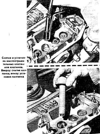
Install the valve spring compressor on the cylinder head and, using pointed pliers, remove the crackers from the valves.
Remove springs with plates.
Remove the valve stem seals using an inertial puller.
Take out the valves.
Remove the valve spring washers.
Clear details.
Check the degree of wear of the valve guide bushings and the clearance between the bushings and valve stems.
Insert the new valve into the guide bush so that the end of the valve stem is flush with the edge of the guide bush, and determine the gap between the valve stem and the guide bush using tool VW 387 with an indicator, resting its foot on the valve head.
Replace the guide bushings if the clearance exceeds the maximum allowable limit of 1.0 mm for intake valves and 1.3 mm for exhaust valves.
Check that the flatness of the mating surface of the cylinder head is not broken using a straightedge and a set of feelers.
Grind, if necessary, the mating surface of the cylinder head within acceptable limits (see subsection «Design and specifications»).
Check the condition of the valves and valve springs.
Check the condition of the valve seats and grind them if necessary. Grinding is carried out with a special tool and within acceptable limits (see subsection «Design and specifications»).
Grind, if necessary, the working chamfers of the intake valves. The working chamfers of the exhaust valves are not subject to grinding, grinding of the exhaust valves is allowed, in other cases they must be replaced.
Before assembly, and after grinding the valve seats and lapping the valves, thoroughly clean the cylinder head.
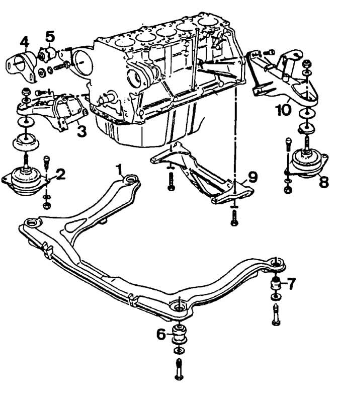
Engine Mount:
1 - subframe;
2, 8 - suspension mounts;
3 - right suspension bracket;
4 - stabilizer;
5 - buffer;
6, 7 - silent blocks;
9 - cross member for fastening the power unit;
10 - left suspension bracket.
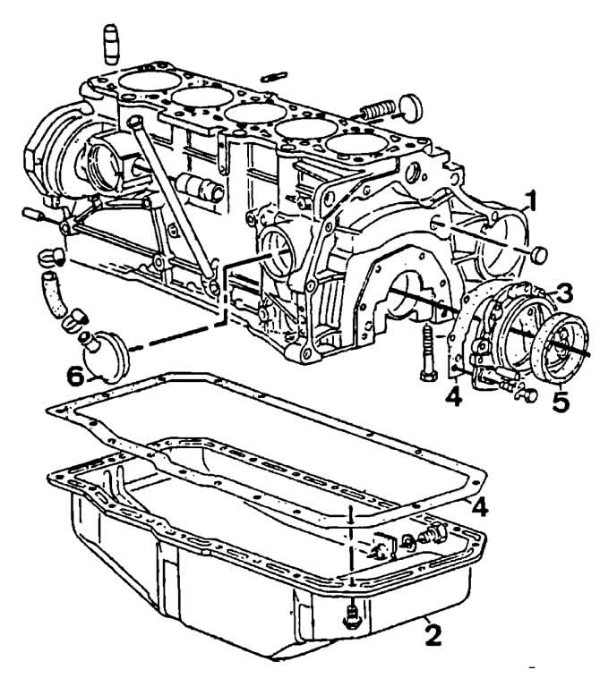
Cylinder Block Details:
1 - cylinder block;
2 - oil sump;
3 — the holder of a forward epiploon of a cranked shaft;
4 - gasket;
5 - front crankshaft oil seal;
6 - oil separator.
Visitor comments