
Checking cylinder diameters
Accurately measure cylinder diameters. Measurements to be made with a caliper in three belts as in the transverse direction «A», and in the longitudinal direction «IN», as shown in the diagram in the section «Four-cylinder engines EP, YN, WV, YP, DT, DS.
In cases where wear exceeds the allowable values by more than 0.08 mm, bore the cylinders to the nearest repair size and install pistons of the corresponding repair size.
Checking clearances between liners and crankshaft journals
Thoroughly clean the running surfaces of the liners and the corresponding crankshaft journal. Put a piece of plastic calibrated wire, equal in width to the insert, on the surface of the neck.
Depending on the type of neck to be checked, install a connecting rod with a cap or a main bearing cap on the neck and tighten the fastening nuts or bolts, respectively. Tighten the nuts of the connecting rod bolts with a torque of 5.0 kgf·m, the bolts of the main bearing caps with a torque of 6.5 kgf·m. Do not allow the crankshaft of the engine to rotate.
Carefully remove the cover and, using the scale printed on the package, determine the size of the gap by the flattening of the wire. More details are given in the accompanying documentation of the gauge wire manufacturer.
The nominal design gap is 0.016-0.075mm (maximum allowable 0.16 mm) for indigenous and 0.015-0.062 mm (maximum allowable 0.12 mm) for crankpins.
If the gap is greater than the limit, replace the liners on these necks with new ones. If the crankshaft journals are worn and ground to repair size, replace the liners with repair ones (increased thickness).
Checking the axial clearance of the crankshaft
Check the axial clearance of the crankshaft using a feeler gauge on the fourth bearing, which should be no more than 0.25 mm.
If necessary, achieve proper clearance by placing thicker thrust washers on the fourth leg.
Checking the dimensions of pistons and piston rings
Determine the degree of wear of the piston by measuring the diameter of 10 mm from the edge of the piston skirt perpendicular to the axis of the piston pin. The piston must be replaced if its diameter differs by more than 0.04 mm from the permissible values (see subsection «Design and specifications»).
Replace the piston rings or pistons if the gaps between the piston rings and grooves exceed the allowable values (see subsection «Design and specifications»).
Engine Assembly
Install the main bearing shells in the bed of the block, lubricate with engine oil and lay the crankshaft in the bearing;.. Lubricate the crankshaft main journals with engine oil.
The axial movement of the crankshaft is selected on the fourth support, the bearing shells of which have two thrust collars.
Pick up the main bearing caps with liners and install them on the bed of the block. Tighten the cover bolts to a torque of 6.5 kgf·m.
Install three piston rings into the corresponding grooves in the pistons, placing their locks through 120° (see photo).
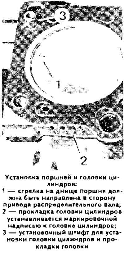
Orient the piston ring locks forward or backward in the direction of the vehicle. There is a mark on the lower compression and oil scraper rings «top» or «oben» («top»), which must face upwards when the ring is installed in the groove. ' Install the pistons, orienting the arrow pressed into the bottom of the piston forward in the direction of the vehicle (towards the camshaft drive).
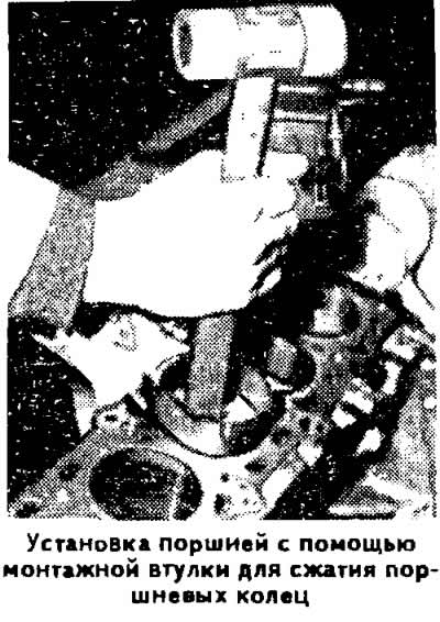
Lubricate the pistons and piston rings with engine oil, compress the piston rings in the grooves of the corresponding mounting sleeve and insert the pistons with the connecting rods into the cylinders.
Install the liners in the connecting rods and connecting rod caps in accordance with the marks made during disassembly, if worn liners are used.
Install the connecting rods and covers on the crankshaft journals, while the sagging on the covers should be directed towards the intermediate shaft.
Lightly tighten the nuts of the connecting rod bolts, then finally tighten them to a torque of 5.0 kgf·m.
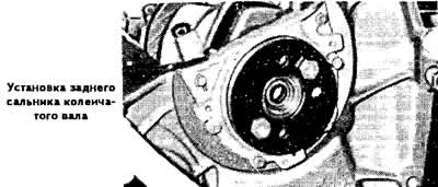
Install the rear oil seal holder with a new cardboard gasket. Using tool 2003/1, press the oil seal into the holder.
Install flywheel.
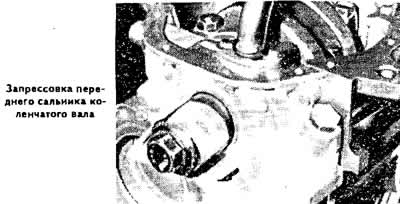
Install a new front oil seal and crankshaft retainer gasket. Install the holder with the oil pump so that the protrusions of the drive gear engage with the flats of the clutch on the crankshaft.
Install the oil pickup tube.
Install the oil pan with a new gasket.
Install water pump, thermostat and thermostat housing.
Install the cylinder head.
Install the camshaft drive belt.
Visitor comments