
The fuel pump is multistage, rotary. It is driven by a constant excitation electric motor. Along the circumference of the eccentric rotor mounted on the motor shaft, roller slots are made. Under the action of centrifugal force, the rollers are pressed against the pump housing, which ensures the tightness of the pump. The fuel sucked in through the gaps between the rollers enters the discharge line.
Despite the fact that the electric motor is immersed in fuel, the pump is explosion-proof, since a combustible mixture never forms in its housing. At all engine operating modes, the pump delivers an excess amount of fuel compared to the maximum amount of fuel required to maintain a constant pressure in the fuel supply system.
If the engine does not start or starts with difficulty, idles erratically, stalls regardless of the mode of operation, and also does not develop full power, then a fuel pump malfunction may be the cause.
The amount of air sucked into the intake manifold is measured by an air flow meter.
The air flow meter is installed in front of the throttle valve. It is equipped with a guiding device with a pressure disc mounted on a movable arm, which deflects depending on the air flow. The displacement of the pressure plate of the air flow meter is transmitted through the lever to the distributor plunger, which determines the amount of fuel in the system.
The composition of the fuel quantity distributor, in addition to the distribution plunger, includes a supply pressure regulator, a differential pressure valve, a supply pipeline and four injection nozzles in accordance with the number of engine cylinders. When the pressure plate of the air flow meter is raised, the distributing plunger of the fuel quantity distributor moves accordingly, opening its control edges for fuel access to the upper chamber of the differential pressure valve, separated from the lower chamber by a diaphragm. The fuel pressure and the force of the spring acting on the upper surface of the diaphragm are greater than the pressure on the lower surface of the diaphragm. As a result of this, the diaphragm moves down and opens the channels for supplying fuel to the injectors. Difficult start, inability to start the engine, as well as its unstable idling, indicate a possible malfunction of the injectors.
The supply pressure regulator maintains the fuel pressure in the system at a certain level and provides excess fuel to the drain line.
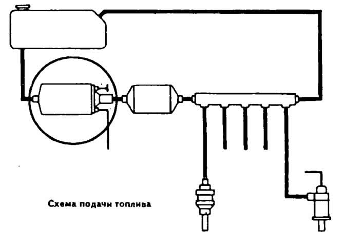
The fuel filter is designed to clean the fuel circulating in the system. The arrow on the filter housing shows the direction of fuel flow in the system.
The fuel accumulator is installed behind the fuel pump. It has damper and accumulative chambers, which are separated by a diaphragm. In front of the diaphragm there is an additional partition with a disc valve that provides fuel supply to the system. A throttling hole for draining fuel is made in the partition.
After turning on the fuel pump, the storage chamber is filled with fuel and the spring diaphragm is stretched to the stop. When the engine is stopped, the tension of the diaphragm keeps the fuel under pressure and prevents the formation of fuel vapors, which makes it easier to start a hot engine.
Starting and warming up of the engine is provided by an electromagnetic starting nozzle, an additional air supply valve and a control pressure regulator.
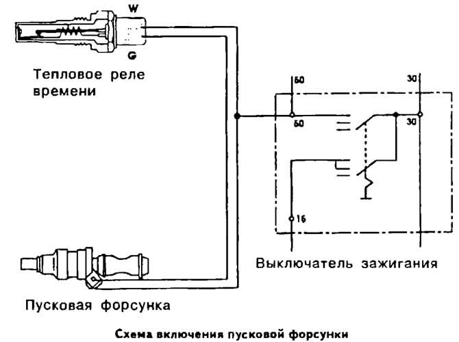
The electromagnetic starting injector is designed to inject additional fuel into the intake pipe at the time of starting a cold engine. It works in conjunction with a thermal time relay, which closes and opens it with an electrical circuit, depending on the temperature of the engine and the duration of its start.
Difficulty starting or inability to start the engine, as well as increased fuel consumption, may be caused by a malfunction of the starting injector. If the engine does not start or runs erratically at idle, a faulty thermal time relay may be the cause.
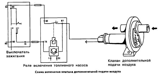
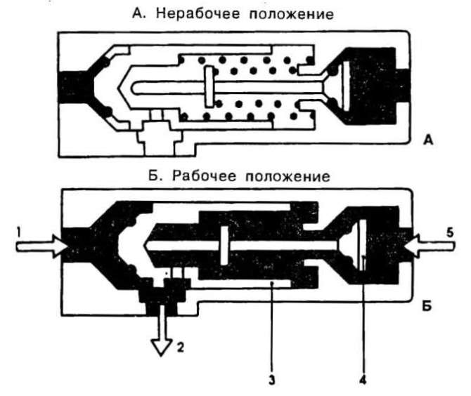
The auxiliary air supply valve is used to increase the engine speed during engine warm-up. When starting a cold engine, the additional air supply channel is opened by a rotary valve flap, which moves when the bimetallic spring is heated. As it warms up, the additional air supply channel gradually closes.
A malfunction of the auxiliary air supply valve can cause the following malfunctions:
- the engine does not start or starts with difficulty;
- engine stalls after starting;
- the engine does not increase idle speed when warmed up.
In addition, the supply of additional air is regulated by the pressure disk of the air quantity meter, the movement of which leads to a corresponding rise in the distribution plunger, which also contributes to an increase in the crankshaft speed (with closed throttle).
The control pressure regulator enriches the working mixture entering the combustion chambers when the engine warms up. On a cold engine, the bimetal spring compresses the diaphragm valve spring, opening the fuel drain channel, which leads to a decrease in resistance on the distribution plunger. A decrease in control pressure at a constant air flow causes an increase in the stroke of the pressure disc. As a result, the distribution plunger is additionally raised, increasing the amount of fuel supplied to the injectors.
As the bimetal spring heats up, the pressure on the diaphragm valve spring of the control pressure regulator decreases and the drain channel slowly closes. The control pressure reaches a normal value and the enrichment of the combustible mixture stops.
Work on load and idle modes
Fuel electric pump 1 (see diagram) takes fuel from the fuel tank and pumps it under a pressure of about 5 kg/cm2 into the dispenser-distributor 2 through the fuel filter 4 and the fuel accumulator 3.
Fuel under supply pressure fills the lower chambers 5 of the dispenser-distributor and presses the diaphragms of the differential pressure valves 6 against the pipes 7 for supplying fuel to the injectors. Through the slots in the walls of the distribution plunger 8, fuel under pressure penetrates into the upper chambers of the dispenser-distributor. The amount of fuel entering the upper chambers of the dispenser-distributor varies depending on the vertical movement of the distribution plunger.
When the total fuel pressure in the upper chambers and the spring pressure exceed the fuel supply pressure in the lower chambers, valve diaphragms 6 are lowered, opening fuel access through the tube to the injection nozzle 9. As soon as the pressure in the upper chambers of the dispenser-distributor decreases, valve diaphragms b return to their original position. Due to the uniform frequency of opening and closing of the fuel supply channels to the injectors, a constant fuel pressure is established. The displacement of the pressure disk 10 of the air flow meter is transmitted through the lever to the distribution plunger, which returns to its original position due to the counteracting fuel pressure in the upper part of the dispenser-distributor. The counter pressure is created by the supply pressure and is regulated by the control pressure regulator 11. The bypass valve installed in the throttle valve area provides a minimum. vacuum in the air flow meter when the engine is idling. The opening degree of the valve is adjusted by a needle screw.
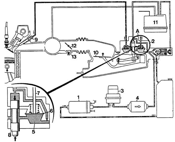
Scheme of the fuel injection system «K-Jetronic» on load and idle modes:
1 - fuel pump;
2 - dispenser-distributor of fuel;
3 - fuel accumulator;
4 - filter;
5 - fuel distributor chamber;
6 - differential pressure diaphragm valve;
7 - fuel supply pipe to the nozzle;
8 - distribution plunger;
9 - nozzle;
10 - pressure disk of the air flow meter;
11 - control pressure regulator;
12 - throttle valve;
13 - idle adjustment screw.
Starting a cold engine
Fuel electric pump 1 instantly creates a working fuel pressure in the system. At the moment of starting a cold engine and for a certain time, the starting injector 15 injects an additional amount of fuel into the intake manifold. The duration of the starting injector is determined by a thermal timer depending on the temperature of the coolant.
An additional air supply valve 16 is installed in an air duct parallel to the throttle valve 12. The valve 16 provides additional air to the engine to increase the idle speed of the cold engine crankshaft.
Additional enrichment of the air-fuel mixture when starting and warming up a cold engine is achieved due to a freer rise of the distribution plunger 8 of the dispenser-distributor due to the fact that the control pressure regulator 11 reduces the counteracting return pressure.
While the engine is not warmed up, the bimetallic spring 18 compresses the spring of the diaphragm valve 17, opening the fuel drain channel, which leads to a decrease in the opposing pressure on the distribution plunger.
Hot engine start
To completely eliminate fuel evaporation after the engine is stopped, the pressure in the injection system is maintained for some time by the fuel accumulator, which temporarily interrupts the flow of fuel into the tank.
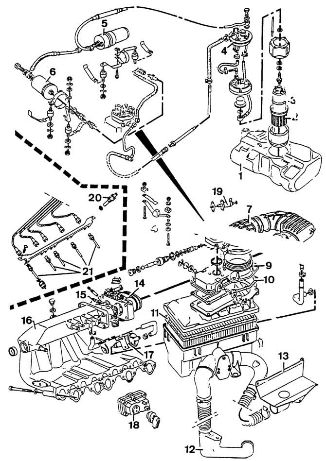
JS engine power system:
1 - fuel tank;
2, 6 - fuel filters;
3 - fuel pump;
4—fuel level sensor;
5 - fuel accumulator;
7 - casing;
8 — dispenser-distributor of fuel;
9 - air flow meter;
10, 15 - gaskets;
11 - air filter element;
12 - air intake;
13 - damper of warm air;
14 - throttle body;
16 - inlet pipeline;
17 - valve for additional air supply;
18 - control pressure regulator;
19 - starting nozzle;
20 - thermal time relay;
21 - nozzles.
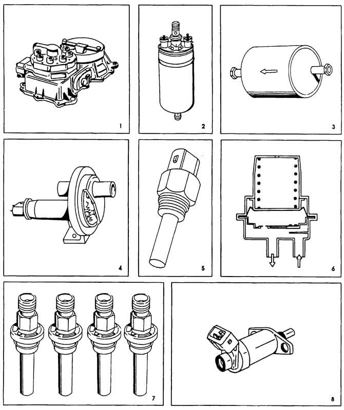
Components of the fuel injection system «K-Jetronic»:
1 - mixture regulator (assembly formed by a fuel dispenser and an air flow meter);
2 - fuel electric pump;
3 - fuel filter;
4 — valve for additional air supply;
5 - thermal time relay;
6 - fuel accumulator;
7 - injection nozzles;
8 - starting nozzle.
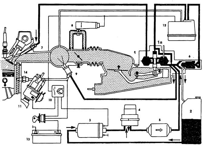
Structural diagram of the fuel injection system «K-Jetronic»:
1 - mixture regulator;
1a - fuel distributor;
2 - fuel tank;
3 - fuel electric pump;
4 - fuel accumulator;
5 - fuel filter;
6 - supply pressure regulator;
7 - injection nozzle;
8 - valve for additional air supply;
9 - electromagnetic starting nozzle;
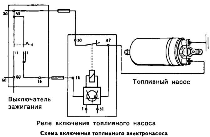
10 — the relay of inclusion of the fuel pump;
11 - sensor-distributor ignition;
12 - control pressure regulator;
13 - battery;
14 - thermal time relay.
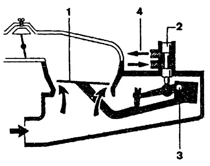
The principle of operation of the air flow meter:
1 - pressure disk;
2 - distribution plunger;
3 - axis of the lever;
4 - and intake valves.
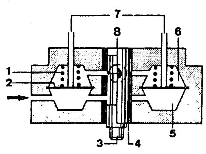
The principle of operation of the dispenser-distributor of fuel:
1 - valve spring;
2 - diaphragm;
3 - distribution plunger;
4 - slotted sleeve of the distribution plunger;
5 - lower chamber;
6 - upper chamber;
7 - fuel supply to the nozzles;
8 - control edge of the distribution plunger.
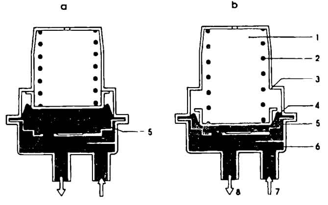
The principle of operation of the fuel accumulator:
1 - sleeve;
2 - spring;
3 - emphasis;
4 - diaphragm;
5 - storage chamber;
6 - reflector;
7 - fuel supply;
8 - fuel outlet.
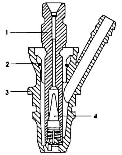
Injection nozzle section:
1 - sprayer body;
2 - sealing ring;
3 - nozzle body;
4 - conical filter.
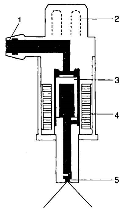
Injector section:
1 - fuel supply pipe;
2 - block;
3 - magnetic core;
4 - winding;
5 - swirl atomizer.
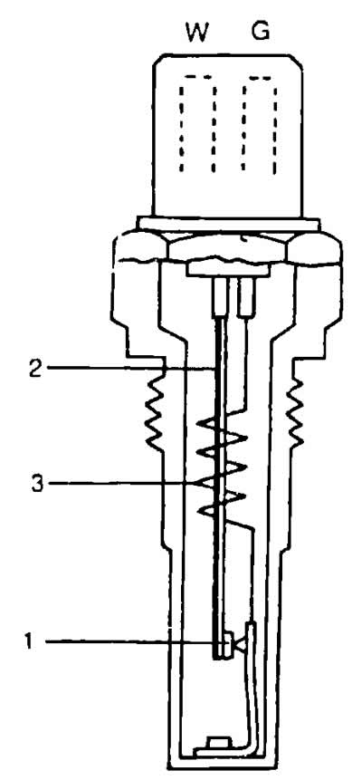
Section of the thermal time relay:
1 - contact;
2 - bimetallic spring;
3 - thermal winding.
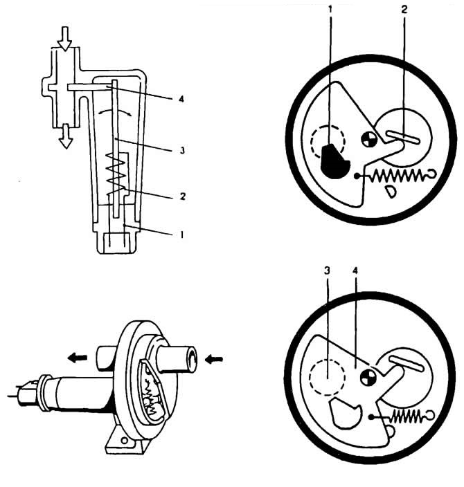
The principle of operation of the auxiliary air valve:
1 - block;
2 - thermal winding;
3 - bimetallic spring;
4 - rotary damper.
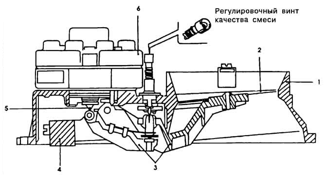
Cross section of the mixture regulator:
1 - diffuser of the air flow meter;
2 - pressure disk;
3 - system of levers;
4—counterweight;
5 - distribution plunger;
6 — dispenser-distributor of fuel.
Operating principle of the supply pressure regulator
1 - fuel supply under supply pressure;
2 - fuel outlet to the fuel tank;
3 - plunger of the supply pressure regulator;
4 - uncoupling valve;
5 - fuel supply under control pressure.
Visitor comments