
Removing
Disconnect battery.
Remove the air intake sleeve, air filter housing (in vehicles with diesel engines and some gasoline) and battery.
In vehicles with 6-cyl. petrol engine, the battery is located in the luggage compartment; therefore, only the air filter housing needs to be removed.
Remove the battery holder frame.
Put a sufficient amount of rags that do not leave fibers in the area of the engine and gearbox.
Draw off the maximum amount of brake fluid using a filling and bleeding device or a device from the brake fluid reservoir.
For vehicles with manual transmission:
Clamp the hose B of the clutch release master cylinder with a clamp Ø up to 25 mm.
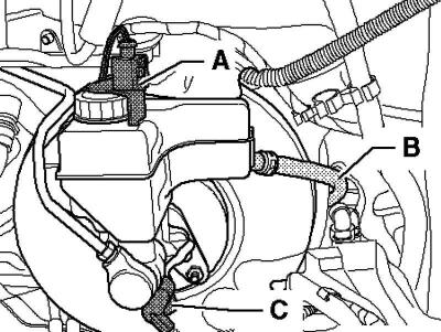
Pic. 6.46. Plug connection and hose for clutch release master cylinder
Remove hose B from clutch master cylinder (pic. 6.46).
Continuation of assembly operations for all vehicles
Remove connector A from the float warning indicator sensor.
Remove connector C from brake light switch F.
Remove the brake fluid reservoir. To do this, press out the latches on the tank and at the same time remove the tank from the plug.
Unscrew the brake pipes 1 on the brake master cylinder, close the pipes with plugs from repair kit 1H0 698 311 A.
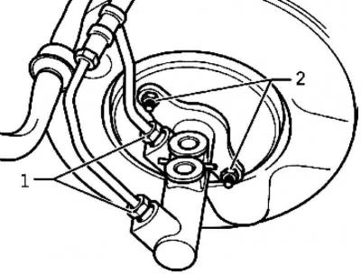
Pic. 6.47. Nuts of fastening of the main brake cylinder
Unscrew nuts 2 from the main brake cylinder (pic. 6.47).
If present, remove the heat shield.
Carefully remove the brake master cylinder from the brake booster.
Unscrew the brake light switch F from the brake master cylinder.
Installation
Installation is carried out in the reverse order
When installing, pay attention to the following points:
When assembling the master brake cylinder and brake booster, make sure that the push rod is properly seated in the master brake cylinder.
Bleed the brake system.
Tightening torques
The main brake cylinder to the brake booster: 25 Nm.
Brake signal switch to brake master cylinder: 5 Nm.
Brake pipelines to the main brake cylinder: 8.5 mm - 17 Nm, 6 mm - 14 Nm.
Visitor comments