



Removal
Rotate the axle in the direction of the arrow using a T45 socket wrench.
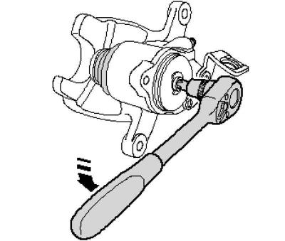
Fig. 6.34. Pushing out the piston using a T45 socket wrench
The lock nut will push the piston out of the brake caliper (Fig. 6.34).
Remove the piston with the protective cap from the brake caliper.
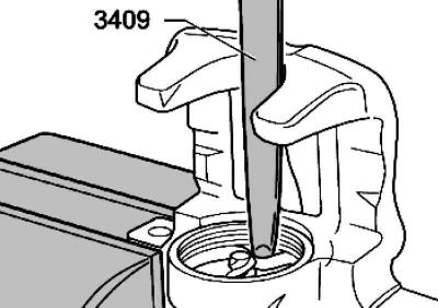
Fig. 6.35. Removing the sealing ring
Remove the sealing ring using the mounting wedge 3409 (Fig. 6.35).
Installation
Clean the surfaces of pistons and sealing rings only with alcohol and then dry.
Before installation, apply a thin layer of assembly paste G 052 150 A2 to the piston and sealing ring.
Insert the sealing ring into the brake caliper.
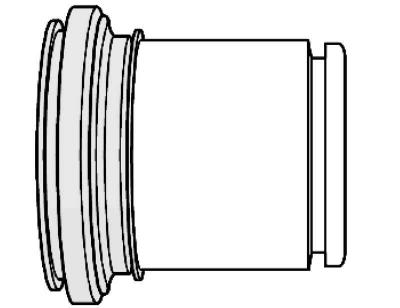
Fig. 6.36. Installing the seal on the piston
Place the outer working lip of the seal on the piston (Fig. 6.36).
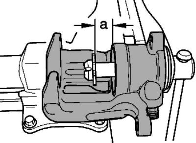
Fig. 6.37. Setting the value of A
Rotate the lock nut on the axle until the value A of 15 mm is reached (Fig. 6.37).
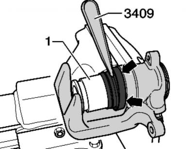
Fig. 6.38. Installing the working edge of the protective cap using a wedge into the groove on the brake caliper
Insert the inner working edge of the protective cap using a wedge into the groove on the brake caliper (Fig. 6.38).
Press the piston onto the lock nut, this is only possible in four positions.
Gently press the piston into the brake caliper while moving the piston.
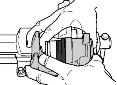
Fig. 6.39. Piston compression
Press the piston in the brake caliper until it is pressed against the lock nut (Fig. 6.39).
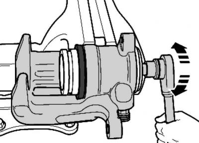
Fig. 6.40. Tightening the nut
Carefully rotate the axle clockwise until the nut is tightened to the stop (Fig. 6.40).
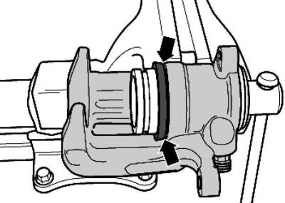
Fig. 6.41. Installed position of the protective cap
Make sure that the protective cap fits snugly against the brake caliper around its entire perimeter (Fig. 6.41).
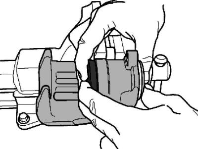
Fig. 6.42. Pressing the piston into the brake caliper
Press the piston into the brake caliper by hand (Fig. 6.42).
In this case, the outer working edge of the protective cap seal will enter the groove on the piston.
Checking the check valve
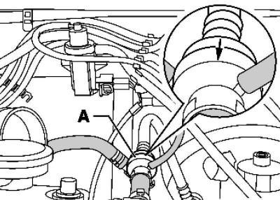
Fig. 6.43. Checking the check valve
Air must pass through check valve A in the direction of the arrow (Fig. 6.43).
In the opposite direction the valve should remain closed.
The text is copied from this portal: www.VWManual.ru
Make sure the installation position is correct.
Removal and installation the brake booster pressure sensor
Remove the engine cover.
Remove the vacuum hose with the brake booster pressure sensor from the brake booster.
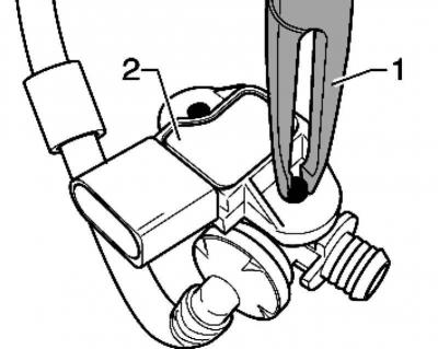
Fig. 6.44. Unlocking the clips
Unlock the clips using pliers 1 (Fig. 6.44).
Carefully pry the brake booster pressure sensor 2 from top to bottom.
Visitor comments