



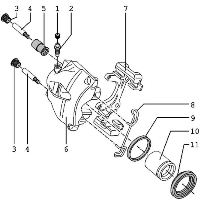
Fig. 6.25. Brake caliper components: 1 – cap; 2 – bleed nipple, 10 Nm; 3 – caps; 4 – guide bolt, 30 Nm; 5 – support sleeve; 6 – brake caliper; 7 – bracket holder; 8 – retaining spring; 9 – sealing ring; 10 – piston; 11 – protective cap
Note: When performing repair work, install the entire repair kit.
Note: Use only alcohol to clean brakes.
Note: Apply a thin layer of assembly paste G 052 150 A2 to the brake cylinders, pistons and seals.
Removal
Press the piston out of the brake caliper using compressed air.
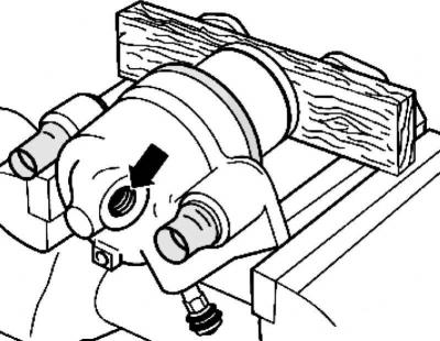
Fig. 6.26. Laying a wooden panel
Place a wooden panel underneath to avoid damaging the piston (Fig. 6.26).
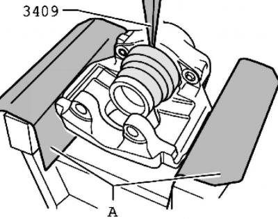
Fig. 6.27. Removing the protective cap
Remove the protective cap from the brake caliper using wedge 3409 (Fig. 6.27).
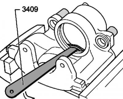
Fig. 6.28. Removing the sealing ring
Remove the sealing ring using wedge 3409 (Fig. 6.28).
When removing, make sure that the cylinder surface is not damaged.
Installation
Clean the surfaces of pistons and sealing rings only with alcohol and then dry.
Before installation, apply a thin layer of assembly paste G 052 150 A2 to the piston and sealing ring.
Insert the sealing ring into the brake caliper.
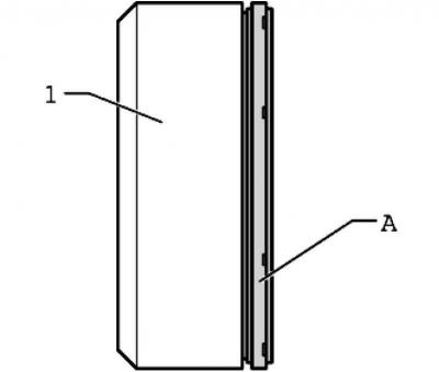
Fig. 6.29. Installing the cap into the assembly tool
Install the protective cap A into the installation tool T10146/6 1 (Fig. 6.29).
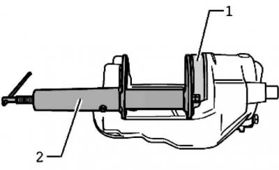
Fig. 6.30. Installing the protective cap
Install the protective cap using the installation tool 1 and the piston pressing device 2 on the brake caliper so that it fits snugly against the brake caliper along its entire perimeter (Fig. 6.30).
Checking the fit of the protective cap
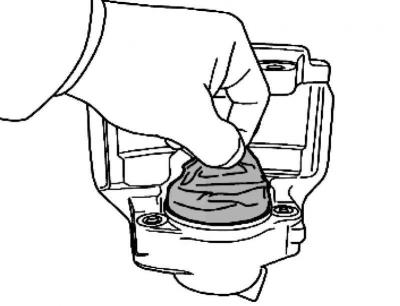
Fig. 6.31. Checking the strength of the protective cap installation
The protective cap must fit so securely that it cannot be removed from the caliper by hand (Fig. 6.31).
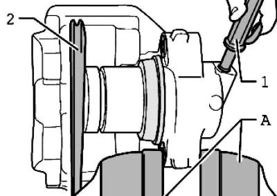
Fig. 6.32. Blowing out the protective cap
Press the piston lightly onto the protective cap and fix it in this position, for example, using wedge 2 (Fig. 6.32).
Do not tilt the piston, otherwise the sealing cuff may be damaged.
The original article is posted on the website www.VWmanual.ru
Blow out the protective cap with compressed air (max 3 bar) 1. In this case, the protective cap will be placed on the piston (Fig. 6.32).
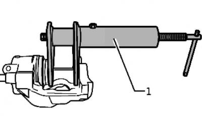
Fig. 6.33. Installing the piston into the brake caliper
Press the piston into the brake caliper using piston pressing device 1 (Fig. 6.33).
In this case, the outer edge of the protective cap seal will enter the groove on the piston.
Visitor comments