
English Русский
Български
Беларускі
Український
Српски
Hrvatski
Română
Polski
Slovenský
Magyar
  |  Articles  |  Sitemap  |  Contacts  |    |
Car maintenance Ford Car maintenance Hyundai Car maintenance Chevrolet Car maintenance BMW Car maintenance Audi Car maintenance Opel Car maintenance AvtoVAZ
VWmanual.ru


Main   Passat   Golf   Polo   Touareg   Tiguan   Sharan   Transporter   Others  
Golf 1 (1974-1984, diesel) Golf 1 (1974-1984, petrol) Golf 2 (1984-1993, petrol) Golf 2 (1984-1993) Golf 3 (1991-1997) Golf 4 (1997-2004) Golf 5 (2003-2008)

Valve and sensor housing — removal and installation (VW Golf 5)

  • Main
  • Golf
  • Golf 5
  • Transmission
  • Automatic gearbox
  • Valve and sensor housing — removal and installation
            0


1. Disconnect the negative (-) battery terminal.

2. Remove the transmission pan and oil pickup.

3. Mark the mounting position of all sensors and solenoid valves, as well as the routing of the associated electrical wiring (see illustration).
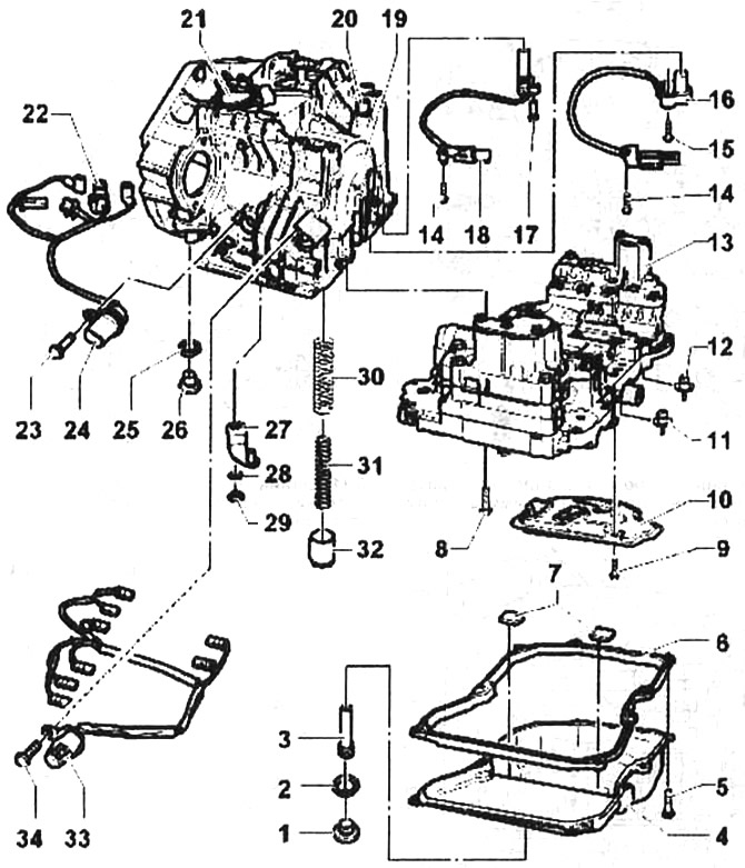
5.3. Valve body

5.3. Valve body
1 - transmission oil level inspection plug. Tightening torque 27 Nm
2 - sealing ring. To be replaced after each dismantling
3 - bypass tube
4 - pallet
5 - bolt. Tightening torque 7 Nm
6 - gasket. To be replaced after each dismantling
7 - magnets
8 - bolts, 12 pcs. Tightening torque 8 Nm + 90° turn. Bolts are subject to replacement after each dismantling
9 - bolts, 3 pcs. Tightening torque 11 Nm
10 - oil intake
11-12 - transmission oil pressure sensors
13 - valve body
14 - bolt. Tightening torque 7 Nm
15 - bolt. Tightening torque 6 Nm
16 - Input shaft speed sensor
17 - bolt. Tightening torque 7 Nm
18 - output shaft speed sensor
19 - crankcase
20 - breather cap
21 - Multifunctional switch
22 - transmission oil temperature sensor
23 - bolt. Tightening torque 6Nm
24 - Wiring harness with 8-pin plug and sealing ring. The ring must be replaced after each dismantling
25 - sealing ring To be replaced after each dismantling
26 - drain plug
27 - gear shift shaft lever
28 - washer
29 - Nut Tightening torque 10 Nm
30 - large spring
31 - small spring
32 - compression buffer
33 - Wiring harness with 14-pin plug and sealing ring. The ring must be replaced after each dismantling


The original material is available on the portal: VWmanual

4. Use a small screwdriver to press the connectors of the solenoid valves 2-9 (see illustration) and disconnect the plugs.

If any plug is damaged, replace the valve wire harness together with the valves.
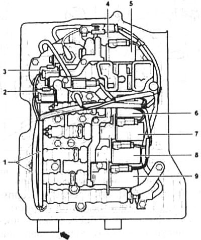
5.4. Using a small screwdriver, press the connectors of the solenoid valves 2-9 and disconnect the…

5.4. Using a small screwdriver, press the connectors of the solenoid valves 2-9 and disconnect the connectors
1 - Wiring harness with 14-pin plug
2 - electromagnetic valve 1
3 - electromagnetic valve 2
4 - electromagnetic valve 4
5 - electromagnetic valve 6
6 - electromagnetic valve 5
7 - electromagnetic valve 9
8 - electromagnetic valve 10
9 - electromagnetic valve 3.


5. Disconnect the connectors of transmission oil pressure sensors 1 and 2 (see illustration).
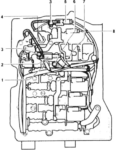
5.5. Disconnect the connectors of transmission oil pressure sensors 1 and 2

5.5. Disconnect the connectors of transmission oil pressure sensors 1 and 2
1 and 4 - transmission oil pressure sensors
2 and 5 - input/output shaft speed sensor plug
3 - bolts
6 - transmission oil temperature sensor mounting bolt
7 - transmission oil temperature sensor
B - Wiring harness with 8-pin plug


6. Disconnect plugs 2 and 5 and unscrew bolts 3 (see illustration 5.5). If any plug is damaged, replace the wiring harness or the input/output speed sensor.

7. Unscrew bolt 6, carefully remove the transmission oil temperature sensor together with the bracket from the valve body, and also release the 8 wire harness from the holder (see illustration 5.5).

8. Remove lever 1 from the gear shift shaft.

In this case, hold the lever with an adjustable wrench 2 so that the force is not transmitted to the multi-function switch.

Be careful not to damage the spool valve 3 (see illustration).
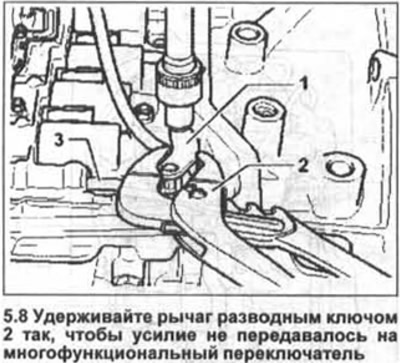
Be careful not to damage the spool valve 3 (see illustration).


9. Unscrew the valve body mounting bolts (see arrows in the illustration) in a diagonal sequence and carefully remove the valve body.
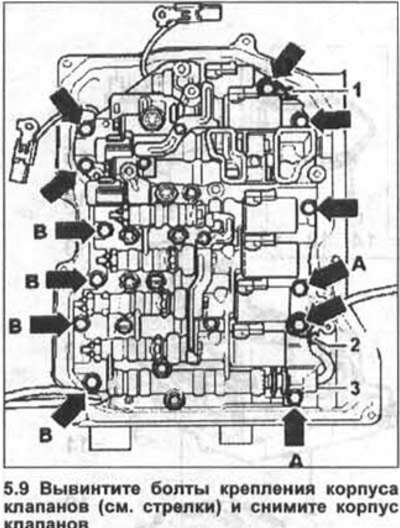
9. Unscrew the valve body mounting bolts (see arrows in the illustration) in a diagonal sequence…


The arrows without markings in the illustration indicate M6x21 bolts, arrows A indicate M6x16 bolts, and arrows B indicate M6x28 bolts.

10. Secure the compression buffer so that it does not fall out or remove it together with both springs.

11. Unscrew bolt 1 or 2 (see illustration) and remove the input or output shaft speed sensors if necessary.
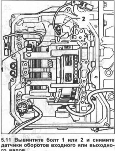
11. Unscrew bolt 1 or 2 (see illustration) and remove the input or output shaft speed sensors if…


The valve body is installed in the reverse order.

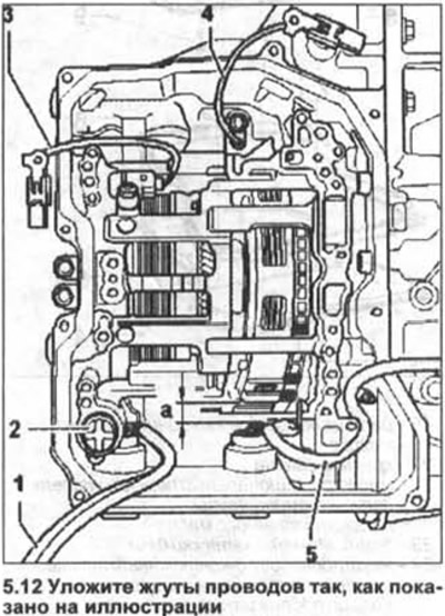
12. Place the wire harnesses as shown in the illustration to avoid pinching them.

Please note that the mounting bolts are of different lengths.

After installing the valve body, fill the box with transmission fluid.
After installing the valve body, fill the box with transmission fluid.


13. Contact a workshop to enter the basic settings of the automatic transmission.

The procedure for removing and installing an automatic transmission is similar to the removal and installation of a manual transmission.

Additionally, it is necessary to remove the transmission oil cooling radiator and disconnect the gear shift cable.

Tightening torques for threaded connections are shown in Figure 5.0.
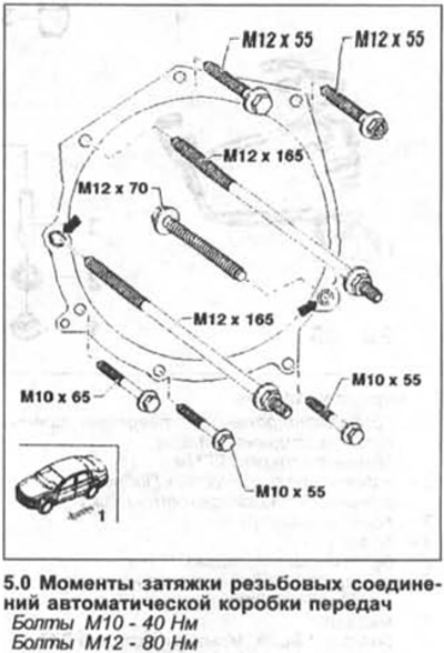
Tightening torques for threaded connections are shown in Figure 5.0.

This article is available at russian, bulgarian, belarusian, ukrainian, serbian, croatian, romanian, polish, slovak, hungarian
The text has been checked: Kolesnikov Artem

Share information:

Previous articles
Multi-function switch — removal, installation and adjustment
Gearbox oil pan and oil intake — removal and installation
Adjusting the gear shift cable
Installing the gear shift cable
Removal the selector cable of the automatic transmission control mechanism
Checking the automatic transmission control mechanism
Next articles


Similar articles from other manuals for VW cars:
Oxygen sensor, camshaft actuator valve (Motronic) Passat B5 (1996-2005)
Electromagnetic valve of the EGR tank, speed sensor (since… Polo 3 (1995-2003)
Checking the valve timing Touareg 1 (2002-2006)
Removal and installation the throttle valve control unit and the… Tiguan 1 (2007-2015)
Checking the temperature sensor of a remote thermometer Sharan 1 (1995-2000)
Replacing the valve stem seals Transporter T4 (1990-2003)
Valve mechanism repair Caddy 3 (2003-2010)
Link to this page in different formats


Visitor comments


No comments yet


How much will 26 + 16 =


Golf 5 
  • General information
  • User manual
  • Maintenance
  • Troubleshooting
  • Power unit
  • Engine repair
  • Cooling and ventilation system
  • Fuel system
  • Ignition system
  • Transmission
  • Clutch
  • Mechanical gearbox
  • Automatic gearbox
  • Chassis
  • Brake system
  • Car suspension
  • Steering
  • Body
  • Interior (internal elements)
  • Exterior (external elements)
  • Doors and covers
  • Electrical equipment
  • Power devices
  • Washers and wipers
  • Lighting and appliances
  • Electrical circuits
Golf 4 
  • General information
  • User manual
  • Weekly checks
  • Maintenance
  • Power unit
  • Petrol engines
  • Diesel engines
  • Cooling system
  • Fuel system (petrol)
  • Control system (petrol)
  • Fuel system (diesel)
  • Exhaust system
  • Transmission
  • Clutch
  • Car gearbox
  • Drive shafts
  • Chassis
  • Car suspension
  • Steering
  • Wheels and tires
  • Brake system
  • Body
  • Exterior (external elements)
  • Interior (internal elements)
  • Ventilation and heating
  • Car doors and sunroof
  • Washers and glass cleaners
  • Electrical equipment
  • Power devices
  • Lighting and appliances
  • Electrical circuits
Golf 3 
  • Petrol engine
  • Engine repair
  • Lubrication system
  • Cooling system
  • Ignition system
  • Diesel engine
  • Engine repair
  • Diesel injection system
  • Pre-glow system
  • Transmission
  • Clutch
  • Gearbox and drive shafts
  • Chassis
  • Steering
  • Wheels and suspension
  • Brake system
  • Electrical equipment
  • Lighting and appliances
  • Electrical circuits
Golf 2 
  • General information
  • Introduction to guide
  • User manual
  • Petrol engines 1.3 l
  • Engine repair
  • Lubrication system
  • Cooling system
  • Carburetors
  • Supply system
  • Ignition system
  • Petrol engines 1.6/1.8 l
  • Engine repair
  • Supply system
  • Ignition system
  • Diesel engines
  • Engine repair
  • Lubrication system
  • Cooling system
  • Power and exhaust system
  • Transmission
  • Clutch
  • 4-speed gearbox 084
  • 5-speed gearbox 085
  • 4-speed gearbox 020/4R
  • 5-speed gearbox 020/4T
  • Automatic gearbox
  • Drive shafts
  • Chassis
  • Steering
  • Car suspension
  • Brake system
  • Body
  • Body elements
  • Doors, locks and windows
  • Electrical equipment
  • Equipment and devices
  • Power devices
Golf 2 (petrol) 
  • General information
  • Characteristics
  • Car care
  • Maintenance
  • Power unit
  • Engine repair
  • Engine 1.05/1.30
  • Engine 1.60/1.80
  • Cooling and lubrication system
  • Power and exhaust system
  • Transmission
  • Clutch
  • Car gearbox
  • Drive shafts
  • Chassis
  • Brake system
  • Steering
  • Suspension
  • Body
  • Body and equipment
  • Electrical equipment
  • Lighting and appliances
  • Electrical circuits
Golf 1 (petrol) 
  • General information
  • Characteristics
  • User manual
  • Maintenance
  • Power unit
  • Engine adjustment
  • Engine 1.1/1.3
  • Engine 1.5/1.6/1.8
  • Engine electrical equipment
  • Cooling system
  • Fuel system
  • Transmission
  • Clutch and manual gearbox
  • Automatic gearbox
  • Chassis
  • Steering
  • Front suspension
  • Rear suspension
  • Brake system
  • Electrical equipment
  • Lighting and appliances
  • Electrical circuits
  • Body
  • Body and equipment
  • Optional equipment
Golf 1 (diesel) 
  • General information
  • Specifications
  • Maintenance
  • Power unit
  • Engine repair
  • Exhaust and turbocharger
  • Cooling system
  • Fuel system
  • Fuel injection system
  • Transmission
  • Clutch and drive shafts
  • Car gearbox
  • Chassis
  • Suspension and wheels
  • Steering
  • Brake system
  • Wheels and tires
  • Body
  • Heating and ventilation
  • Exterior (external elements)
  • Interior (internal elements)
  • Doors and windows
  • Electrical equipment
  • Equipment and devices
  • Lighting system
  • Power devices
  • Electrical circuits
VWmanual.ru © 2016-2026 | Mobile version | News and articles | Sitemap: EN BG BY UA RS HR RO PL SK HU | Write message | Site search
Passat B2 • Passat B3 • Passat B4 • Passat B5 • Passat B6 • Golf 1, diesel • Golf 1, petrol • Golf 2, petrol • Golf 2 • Golf 3 • Golf 4 • Golf 5 • Polo 3 • Polo 4 • Touareg 1 • Tiguan 1 • Sharan 1 • Transporter T3 • Transporter T4 • LT 28 • LT 2D • Beetle • Caddy 3 •
Our website uses cookies to ensure functionality and convenience.