



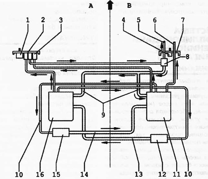
Fig. 2.307. Connection diagram of fuel lines and parts in the fuel tank:
1 - gravity feed valve: 2 - flange: 3 - fuel filter; 4 - gravity feed valve; 5 - fuel supply line; 6 - fuel supply line for additional heater; 7 - flange; 8 - fuel pressure regulator; 9 - fuel drain line; 10 - fuel supply line to ejector pumps; 11 - fuel supply module; 12 - ejector pump; 13 - supply pipeline; 14 - supply pipeline; 15 - ejector pump; 16 - fuel supply module.
NOTE: A - left side of the tank. Arrow indicates direction of travel. B - right side of the tank.
Visitor comments