
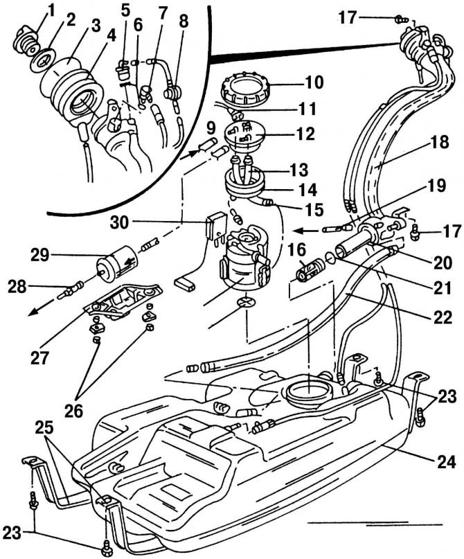
Pic. 206. Details of the power supply system located near the fuel tank: 1 - fuel tank cap; 2 - sealing ring; 3 - safety ring; 4 - rubber seal; 5 - check valve; 6 - O-shaped sealing ring; 7 - ventilation valve; 8 - pressure reducing valve; 9 - return pipeline; 10 - union nut; 11 - plug, black, pump and fuel quantity sensor; 12 - flange; 13 - supply fuel hose; 14 - sealing ring; 15 - return hose; 16 - check valve; 17 - bolt, 10 Nm; 18 - filler pipe; 19 - ventilation pipeline; 20 - sealing ring; 21 - safety ring; 22 - ventilation pipeline; 23 - bolts, 25 Nm; 24 - fuel tank; 25 - fastening of the fuel tank; 26 - bolts, 20 Nm; 27 - fuel filter cover/holder; 28 - fuel line (black color); 29 - fuel filter (observe the direction of fuel flow); 30 - fuel level sensor in the tank; 31 - fuel pump; 32 - strainer
Removing the sensor 30 (pic. 206) the fuel level is carried out in the same way as removing the fuel pump, until flange 12 is removed. Then pull the sensor out of the fuel tank by hand by pressing on its locking latch.
When installing the flange, pay attention to the correct location.
Visitor comments