
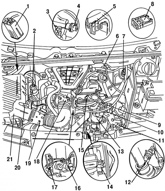
Pic. 207. The location of the elements of the Simos injection system in the engine compartment of a 2.0-liter engine: 1 - tank with activated carbon; 2 - solenoid valve; 3 - nozzle; 4 - fuel pressure regulator; 5 - four-pin plug; 6 - high voltage transformer; 7 - valve of the exhaust gas recirculation system; 8 - ECU with the Simos injection and ignition system; 9 - three-pin plug; 10 - central plug; 11 - three-pin plug; 12 - speed sensor; 13 - ignition distributor with Hall sensor; 14 - engine crankshaft speed sensor; 15 - coolant temperature sensor; 16 - knock sensor; 17 - connection with «weight»; 18 - throttle body; 19 - mass air flow sensor; 20 - intake air temperature sensor; 21 - air filter
Fuel under pressure, the value of which is maintained by pressure regulator 4 (pic. 207), is continuously supplied to the nozzles 3, which are installed directly in front of the intake valves. ECU 8 calculates the duration of the injection pulse, and therefore the composition of the combustible mixture, depending on the following parameters:
- throttle position;
- the degree of vacuum or the amount of pressure in the intake manifold;
- engine crankshaft speed.
An electric fuel pump draws fuel from the tank and pressurizes it to the fuel rail. The pressure regulator controls the amount of fuel returned to the tank and maintains a constant fuel supply pressure to the injectors.
Based on the information received from the sensors, the ECU generates fuel injection time pulses. In the event of a malfunction of any sensor, the ECU switches to the operating mode according to «default» with reduced efficiency based on fixed parameters embedded in the ECU memory block.
The location of the elements of the injection system in the engine compartment of the 2.0-liter Simos engine is shown in fig. 207.
The electronic injection system consists of the following elements:
- activated carbon tank 1 is located in the right wheel arch;
- solenoid valve 2 opens and closes the connection between the activated carbon tank and the motor;
- mass air flow sensor 19 is located between the air filter and intake hose;
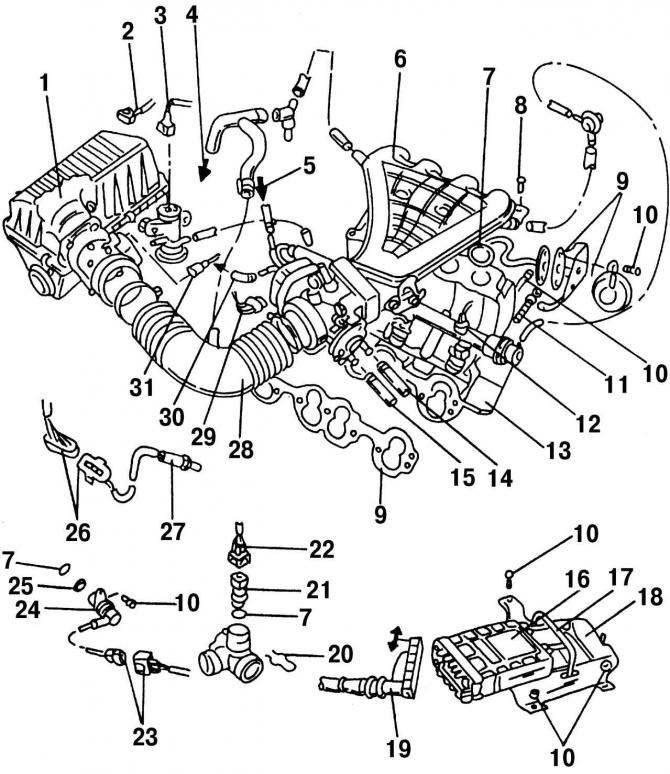
Pic. 208. The location of the elements of the Simos injection system on a 2.0-liter engine: 1 - air filter; 2 - wire tip of the intake air temperature sensor; 3 - wire tip of the cleaning system with activated carbon; 4 - to the crankcase; 5 - fuel hose, white mark; 6 - the upper part of the intake manifold; 7 - O-shaped sealing ring; 8 - bolt, 16 Nm; 9 - gasket, replace with a new one; 10 - bolt, 10 Nm; 11 - bolt, 25 Nm; 12 - nozzle wire tip; 13 - the lower part of the intake manifold; 14 - to the connection on the cylinder head; 15 - to the expansion tank; 16 - ECU; 17 - collar; 18 - ECU holder; 19 - multi-pin plug; 20 - spring lock collar; 21 - coolant temperature sensor; 22 - wire tip for (21); 23 - wire tip for (24); 24 - engine crankshaft speed sensor; 25 - spacer ring; 26 - plug connector for lambda probe and lambda probe heating; 27 - lambda probe; 28 - air intake hose; 29 - plug block of the throttle body; 30 - recirculation hose, blue mark; 31 - wire tip of the mass air flow sensor
- four-pin connector 5 connected to lambda probe 27 (pic. 208) and heating lambda probe;
- valve 7 of the exhaust gas recirculation system today is increasingly called the EGR valve;
- ECU 8 for the Simos injection system and the associated ignition system is located behind the instrument panel;
- three-pin plug 9 of the brown knock sensor;
- plug 10 of the engine crankshaft speed sensor in black;
- a Hall sensor is installed in the ignition distributor 13;
- black coolant temperature sensor 15 is also a remote thermometer sensor located on the instrument panel;
- the functions of knock sensor 16 and ignition coil 6 are described in section 8;
- the speed sensor 12 informs the ECU about the current vehicle speed;
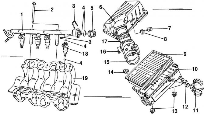
Pic. 209. The lower part of the intake manifold and air filter with mounting: 1 - distribution fuel line; 2 - bolt, 10 Nm; 3 - safety clamp; 4 - O-shaped sealing ring; 5 - fuel supply pressure regulator; 6 - upper part of the air filter; 7 - intake air temperature sensor; 8 - rubber nozzle (pay attention to the correct installation); 9 - air filter element; 10 - lower part of the air filter; 11 - solenoid valve, activated carbon reservoir; 12 - rubber bushing; 13 - rubber nozzle; 14 - rubber gasket; 15 - mass air flow sensor; 16 - bolt, 10 Nm; 17 - sealing ring; 18 - nozzle; 19 - the lower part of the intake manifold
- sensor 7 (pic. 209) informs the ECU about the intake air temperature;
- sensor 14 (pic. 207) informs the ECU about the specific engine speed.
The Simos ECU contains a memory unit or storage device that logs all failures (crashes), that occurred during operation, which has three modes of operation:
- reading stored faults (faults), that occurred during engine operation;
- mode of checking the components and systems of the car;
- mode for diagnosing malfunctions of injection and ignition systems with the engine stopped.
The request for operating modes is carried out through the diagnostic block.
Erasing information about faults from the memory device is possible only after a single reading of the codes (mode number 1) or after troubleshooting (modes #2 and 3).
Visitor comments