
Tire Pressure Monitoring System Components
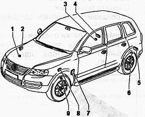
Pic. 4.31. Tire pressure monitoring system components:
1 - front right tire pressure sensor; 2 - antenna for the front right control pressure indicator; 3 - rear right tire pressure sensor; 4 - antenna for the rear right control pressure indicator; 5 - antenna for the rear left control pressure indicator; 6 - rear left tire pressure sensor; 7 - control unit of the tire pressure monitoring system; 8 - antenna for the front left control pressure indicator; 9 - front left tire pressure sensor.
Removing the tire pressure sensor
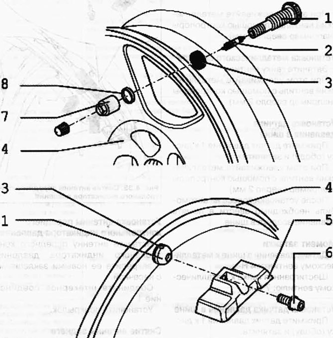
Pic. 4.32. Tire pressure sensor and metal valve:
1 - metal valve: 2 - valve spool; 3 - sealing ring; 4 - rim; 5 - tire pressure sensor; 6 - Torx T20 screw; 7 - nut; 8 - puck.
Unscrew tire pressure sensor 1 (pic. 4.33).
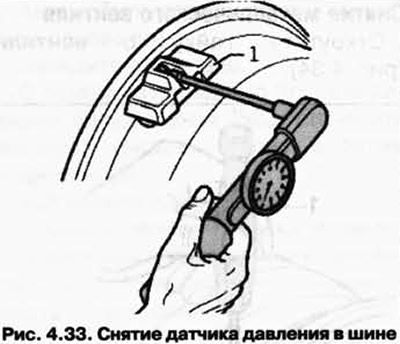
While doing this, hold the metal valve with a counterhold (e.g. drill bit 2 mm)
Removing the metal valve
Loosen the valve nut (pic. 4.34).
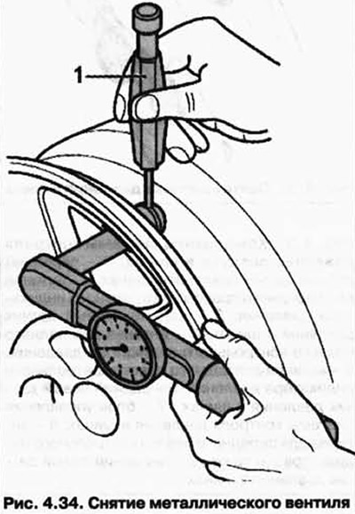
While doing this, hold the metal valve with a counterhold (e.g. drill bit 2 mm).
Installing a metal valve
Tighten the valve nut.
While doing this, hold the metal valve with a counterhold (e.g. drill bit 2 mm).
Tire pressure sensor installation
Press pressure sensor 1 against the disc (rim) and tighten.
While doing this, hold the metal valve with a counterhold (e.g. drill bit 2 mm).
After installing the wheel on the car, you must enter the air pressure in the tire into memory.
Torque
Tire pressure sensor to metal valve: 4 Nm.
Hexagon nut to metal valve: 7 Nm.
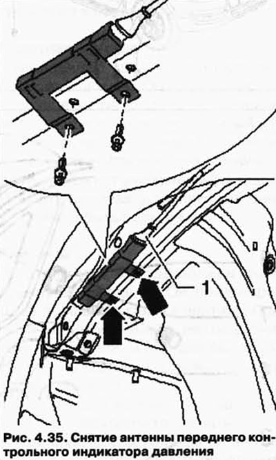
Removing the Front Pressure Indicator Antenna
The front pressure control indicator antennas are mounted behind the fender liner on the side member.
Switch off the ignition.
Remove the cover.
Disconnect plug connection 1.
Remove the knurled rivets and remove the front pressure indicator antenna (pic. 4.35).
Installing the Front Pressure Indicator Antenna
Insert the front pressure indicator antenna and secure it with new knurled rivets.
Connect plug connection 1.
Install the fender.
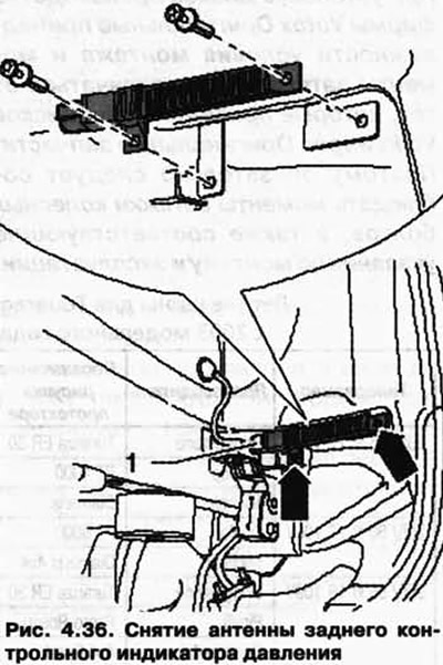
Removing the Rear Pressure Indicator Antenna
The rear pressure indicator antennas are mounted behind the wheel arch liners on the side opposite to the direction of travel.
Switch off the ignition.
Remove the cover.
Disconnect plug connection 1.
Remove knurled rivets and remove rear pressure indicator antenna (pic. 4.36).
Installing the Rear Pressure Indicator Antenna
Insert the rear check pressure indicator antenna and secure it with new knurled rivets.
Connect plug connection 1.
Install the fender.
Visitor comments