



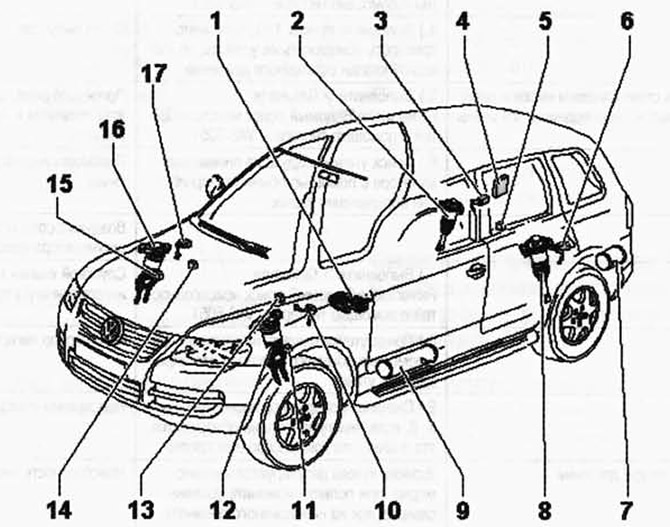
Fig. 4.39. Components of the clearance control system and their installation locations:
1 - compressor with magnetic valve block; 2 - right rear elastic pneumatic element; 3 - rear right body level sensor; 4 - control unit of the clearance control system; 5 - rear body acceleration sensor; 6 - rear left body level sensor; 7 - rear air accumulator; 8 - elastic pneumatic element rear left; 9 - front air accumulator; 10 - Front left body level sensor; 11 - Front left wheel acceleration sensor; 12 - elastic pneumatic element front left; 13 - front left body acceleration sensor; 14 - front right body acceleration sensor; 15 - front right wheel acceleration sensor; 16 - elastic pneumatic element front right; 17 - front right body level sensor.
NOTE: During the 2004 model year, the 7L6 907 553 A/B (200 Hz) ride height control module was replaced by the 7L0 907 553 F/* (800 Hz) ride height control module.
As a result of using new control units, the need for wheel acceleration sensors has been eliminated, and the body level sensors have been adapted.
If the control unit (200 Hz) is replaced by the unit (800 Hz), the body level sensors must also be replaced. The wheel acceleration sensors remain on the car to "seal" the pipeline.
Visitor comments