
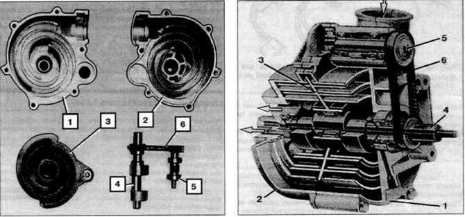
Pic. 15. Supercharger «G60»: 1, 2 - halves of the supercharger body with spiral channels; 3 - movable displacer; 4 - eccentric drive shaft; 5 - eccentric shaft of plane-parallel movement: 6 - toothed belt.
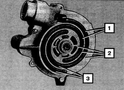
Pic. 16. Section in the middle plane of the supercharger: 1 - spiral displacers; 2 - body; 3 - channels with variable volumes.
The principle of operation of this volumetric supercharger is based on changing the volume of a rectangular channel twisted into a spiral, going from the periphery to the center. Displacer (piston) is also a spiral, moves in a plane-parallel manner in a circle, running around with a spiral of the displacer along the spiral line of the channel, touching the channel wall. Thus. the displacer spiral at the point of contact divides the spiral channel into two volumes:
- before the line of contact between the displacer and the channel, as the line of contact advances, the air is compressed due to a decrease in the cross-sectional area of the channel;
- behind the line of contact between the displacer and the channel, as the line of contact advances, a vacuum is created and air is sucked into the channel.
After the displacer's rolling coil returns to its original position, the cycles of injection in front of the touch line and suction behind the touch line are repeated.
The accumulator housing consists of two symmetrical halves, each of which has two spiral channels. One spiral channel is twisted by 360°, and the second by 540°. Between the two fixed channels of each half of the housing there are two movable spiral displacers, which, with their spirals, enter the spiral channels of each half of the housing. The displacer spirals of one half of the housing are separated from the displacer spirals of the other half of the housing by a partition. Each displacer spiral is twisted by 360°and the displacer spirals, separated by a partition, are rotated relative to each other by 180°.
To keep the displacers from arbitrary rotation around their axis, a hole is made in the peripheral section of the partition, into which an eccentric with the same eccentricity as the eccentric of the displacer drive shaft enters. Between themselves, the eccentrics are arranged symmetrically and are connected by a toothed belt. The eccentric shafts are parallel to each other.
The drive shaft has one eccentric for displacers separated by a partition. The eccentrics rotate in the central holes of the displacers on needle bearings. To eliminate the imbalance of the displacers, two counterweights are placed on the drive shaft.
The amount of blown air depends on the speed of the drive shaft, which can reach 10,000 rpm. The pressure ratio at the inlet and outlet of the supercharger depends on the profile of the spirals. The pulsations of the forced air flow are small. The supercharger is quiet, the efficiency is 65%.
Boost pressure check
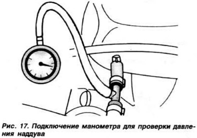
Disconnect the vacuum hose going to the fuel pressure regulator from the inlet pipe and connect a pressure gauge to the hose hole and the inlet pipe connection using a T-piece (pic. 17). Warm up the engine to normal operating temperature and let it idle. Disconnect the wire blocks from the CO adjustment potentiometer and the coolant temperature sensor (blue connector). Press the accelerator pedal firmly to the stop (in no case hold the accelerator pedal depressed for more than 10 seconds, so as not to damage the supercharger). Once the minimum boost pressure is 0.6 kgf/cm2 pressure gauge is reached, the engine speed should increase. If this doesn't happen. check the tightness of the intake tract and the adjustment of the bypass valve for boost pressure control (see below). If there is no air intake. and the valve is installed correctly, the supercharger must be replaced.
Boost pressure control wastegate adjustment
The position of the boost pressure control bypass valve is set at the factory and should not be changed during operation. If it was accidentally violated, do the following:
- install the protractor on the throttle shaft (rice. 9);
- fully open the throttle and set the goniometer needle to zero;
- slowly close the throttle until lever 2 touches (rice. 10) control bypass valve for boost pressure control with intermediate lever 1. In this case, the goniometer should show 10°± 1°. If not. achieve the correct reading by changing the length of the connecting rod 3;
- adjust the full load switch as above.
Visitor comments