
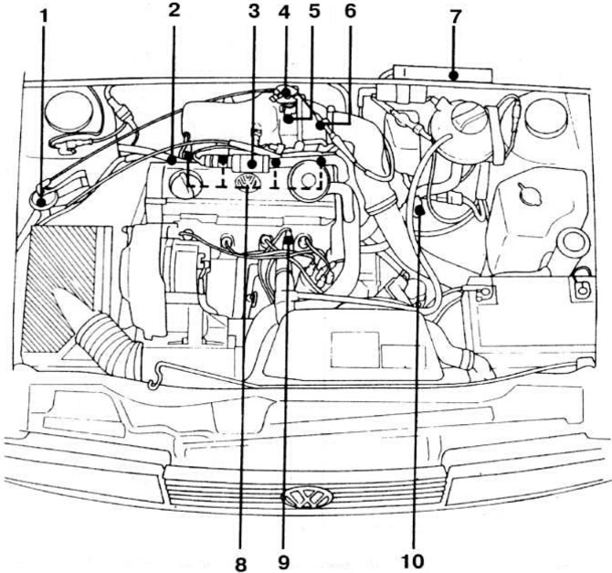
Pic. 1. Placement of elements of the fuel injection control subsystem KSUD «Digifant G60» in the engine compartment: 1 - canister shut-off valve: 2 - fuel pressure regulator: 3 - idle speed solenoid valve: 4 - idle and full load switches: 5 - throttle body: 6 - boost pressure control bypass valve body: 7 - controller: 8 - nozzles: 9 - coolant temperature sensor: 10 - CO adjustment potentiometer.
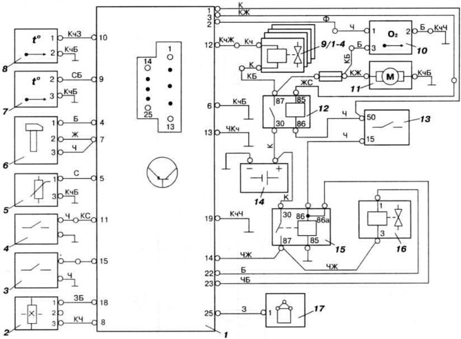
Pic. 2. Connection diagram of KSUD «Digifant G60» engine «1H» car «Passat GT 1.8 G60 Syncro»: 1 - controller; 2 - Hall sensor of the ignition system: 3 - full load switch; 4 - idle switch: 5 - CO adjustment potentiometer in exhaust gases: 6 - knock sensor: 7 - intake air temperature sensor: 8 - coolant temperature sensor; 9/1-4 - nozzles; 10 - oxygen concentration sensor in exhaust gases; 11 - fuel pump; 12 - injection system power relay; 13 - ignition switch: 14 - battery; 15 - controller power relay; 16 — the electromagnetic valve of stabilization of idling; 17 - ignition coil.
NOTE: When working with the fuel injection control subsystem KSUD «Digifant G60» the same precautions should be observed as when working on the central fuel injection system «Mono-Jetronic», see relevant subsection.
Checking and adjusting the engine idle
Before adjusting and checking the idle speed of the engine, do the following:
- warm up the engine (oil temperature not less than 80°С);
- turn off consumers of electricity, including air conditioning. if it is installed;
- make sure that the ignition timing and the gap between the electrodes of the spark plugs are set correctly;
- make sure that the idle speed stabilization solenoid valve is working; when the ignition is turned on, the valve should vibrate and hum.
The electric fan of the cooling system should not turn on during the test.
Connect the control tachometer according to the operating instructions, connect the gas analyzer to the tube (see the corresponding drawing for the motor «RV») carbon monoxide measurements (SO) in exhaust gases.
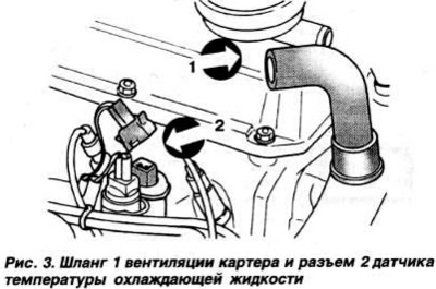
Disconnect hose 1 (pic. 3) crankcase ventilation and rotate the hose so. so that fresh air enters its opening. Start the engine at idle and let it run for about 1 minute. then disconnect the blue connector 2 (pic. 3) coolant temperature sensor, then increase the engine speed three times to above 3000 rpm and leave the engine idling.
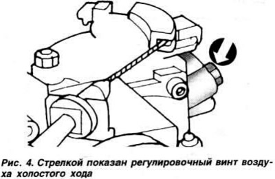
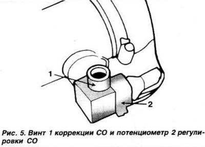
Check the idle speed of the crankshaft and the CO content in the exhaust gases, which, respectively, should be in the range of 750-850 rpm and 0.3-1.1%. If the received values do not fit into the specified padels. remove the plugs from the idle speed adjusting screws and. alternately turning the idle air screw (to adjust the idle speed) and CO correction screw (pic. 4 and 5), to achieve the required values.
Connect the coolant temperature sensor connector. Press the accelerator pedal three times and check the CO content in the exhaust gases again. If it has changed, test the exhaust gas oxygen sensor as follows. If necessary, replace the failed sensor and check the idle speed and CO content again. If the engine idle speed is correct, connect the crankcase ventilation hose to the cylinder head cover fitting. In this case, the CO content in the exhaust gases may increase, which, however, does not indicate an incorrect adjustment of the CO content, but the presence of a certain amount of gasoline in the engine oil. To return the CO value to the specified limits, in this case, it is necessary to drive several kilometers at high speed or change the engine oil.
Throttle valve adjustment
The throttle valve opening is set at the factory and does not require adjustment during operation. If you accidentally change the position of the throttle stop screw, you can restore the adjustment as follows.
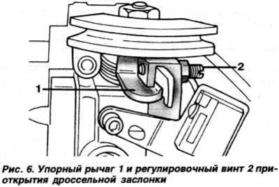
Loosen the lock nut, unscrew the adjusting screw 2 (pic. 6) opening the throttle valve until some clearance is obtained between the screw and the thrust lever 1 of the throttle valve. Tighten the adjusting screw until it touches the stop lever. The moment of contact is determined by clamping a sheet of tissue paper. pre-inserted between the screw and the lever. After that, tighten the throttle adjustment screw a further half turn. Check the operation of the idle switch. Check and, if necessary, adjust the idle speed of the engine.
Checking the fuel pressure in the system
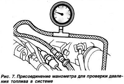
Disconnect the fuel supply pipeline from the fuel line and connect a pressure gauge to the pipeline opening and the fuel line branch pipe using an adapter (pic. 7). Start the engine at idle and check the fuel pressure on the pressure gauge, which should be about 2.5 kgf / cm2. Disconnect the fuel pressure regulator vacuum hose from the throttle valve inlet pipe. In this case, the pressure on the pressure gauge should increase to approximately 3 kgf / cm2. Switch off the ignition. After 10 minutes, check the residual fuel pressure, which should be at least 2 kgf / cm2. Clamp the blue fuel drain hose tightly. If the fuel pressure does not decrease, the fuel pressure regulator is faulty.
Checking the supply voltage of the idle and full load switches
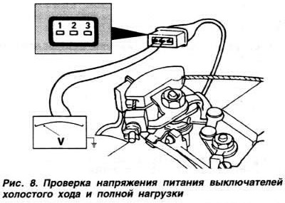
Disconnect switch connector (pic. 8), connect the voltmeter first to the terminals «1» and «2». then to conclusions «2» and «3» male part of the connector, turn on the ignition and check the supply voltage of the switches, which in both cases should be about 5 V. If the measured voltage does not match this, connect the switch connector, identify and eliminate the cause of the circuit integrity If the circuit is not broken, replace the controller.
Checking and adjusting the idle and full load switches
Disconnect the idle and full load switch connector. Connect an ohmmeter to the leads «1» and «2» (pic. 9) switch pads. The resistance on the ohmmeter should be 0 ohm. Fix on the throttle shaft (pic. 9) goniometer disk with an arrow.
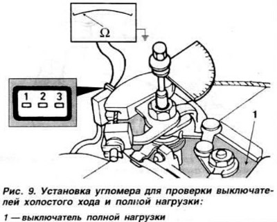
Open the throttle to 10°on the goniometer, then slowly close the throttle until the idle switch operates. At an angle of 1.0±0.5 between the throttle control lever and the idle stop, the resistance on the ohmmeter should be 0 Ohm. If the resistance value is lower, loosen the idle switch mounting screws and, by moving the switch, achieve zero resistance at a given angle between the throttle control lever and the idle stop, then tighten the switch mounting screws.
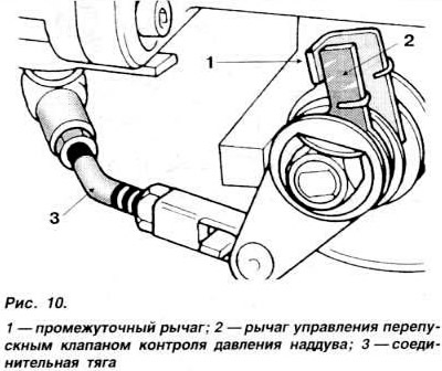
Connect an ohmmeter to the leads «2» and «3» switch pads. The resistance on the ohmmeter should be 0 ohm. Open the throttle valve with a screwdriver. to intermediate lever 1 (pic. 10) barely moved away from lever 2 of the bypass valve control boost pressure. In this position, set the goniometer needle to zero. Close the throttle valve approximately 10°on the goniometer. In this case, the full load switch should operate at an angle of 4±1°according to the goniometer. If this does not happen, loosen the screws securing the switch and. moving it. achieve the operation of the switch at a given deviation of the goniometer needle, and then tighten the screws securing the switch.
Checking the coolant temperature sensor
Produced in the same way as on engines «RV» and «2E» (see relevant subsection). The resistance of the sensor at a coolant temperature of 0°C is 5.0-6.5 kOhm, at 20°C - 2.0-3.0, at 40°C - 1.0-1.5. at 60°C - 0.525-0.650. at 80°C - 0.275-0.375 and at 100°C - 0.175-0.225 kOhm.
Checking the intake air temperature sensor
Disconnect potentiometer 2 connector (pic. 5) CO adjustment Connect an ohmmeter to the terminals «2» and «3» potentiometer pads and measure the resistance of the sensor, which at an intake air temperature of 0°C should be within 5.0-6.5 kOhm, at 20°C - 2.0-3.0, at 40°C -1.0-1.5. at 60°C - 0.525-0.650, at 80°C - 0.275-0.375 and at 100°C - 0.175-0.225 kOhm.
Checking the idle speed solenoid valve
Checking the performance of the idle speed solenoid valve is carried out on a warm engine (oil temperature not higher than 80°С), with properly adjusted engine idling, with a serviceable coolant temperature sensor of the fuel injection control subsystem, in the absence of air leakage in the engine intake tract.
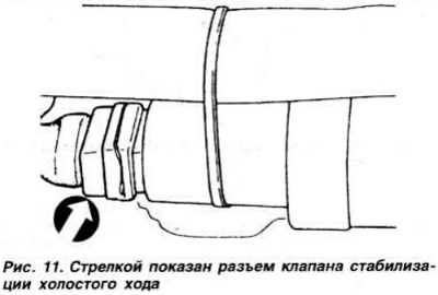
Will turn on», ignition. If the idle speed stabilization valve is working, then it should vibrate and buzz. If it doesn't, disconnect the connector (pic. eleven) valve and measure the resistance of the valve winding by connecting an ohmmeter to the terminals of the valve block, which should be within 2-10 ohms. If the value obtained does not match this value, the valve must be replaced.
Check the continuity of the circuit between the valve and the controller by connecting an ohmmeter to the terminals of the connecting block. If the circuit is damaged, replace the controller.
Checking the injectors
Produced in the same way as on engines «RV» and «2E» (see relevant subsection). Injector winding resistance 10-20 Ohm.
Exhaust oxygen sensor test
Warm up the engine to a temperature of at least 80°C, check that the idling speed is correct, check that the exhaust system is leak-proof, check that the coolant temperature sensor connector is securely connected and that the power supply voltage of the oxygen content sensor in the exhaust gases equal to the battery voltage. Connect the gas analyzer to the CO measuring tube.
Let the engine idle for at least 2 minutes and check the carbon monoxide content (SO) in exhaust gases.
Disconnect the fuel pressure regulator vacuum hose from the intake manifold. In this case, the CO content in the exhaust gases must first increase briefly, then decrease again to normal values.
If this does not reduce the CO content in the exhaust gases, disconnect the connector of the oxygen content sensor in the exhaust gases, which is located next to the idle speed stabilization solenoid valve.
Connect the output of the sensor connector, to which the green wire is connected, in turn to «plus» battery and «mass», monitor the change in the CO content in the exhaust gases. If at the same time the CO content either increases or decreases, replace the oxygen content sensor in the exhaust gases.
Checking the CO adjustment potentiometer
Disconnect the potentiometer connector. Connect an ohmmeter to the leads «1» and «3» potentiometer and measure the resistance, which should be in the range of 0-2000 ohms.
Canister Check Valve
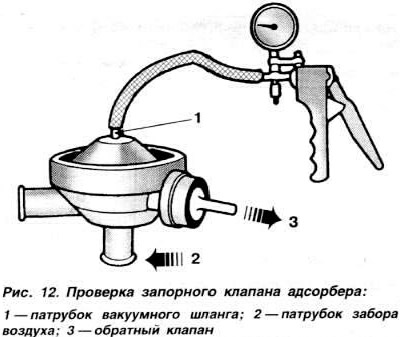
Disconnect vacuum hose from connection 1 (pic. 12) at the top of the shut-off valve and connect the vacuum pump hose to it. Make sure that air enters through the opening of the nozzle 2. Create a vacuum in the valve with a vacuum pump and make sure that the valve closes. In this case, air should not flow through the pipe 2, and the check valve should let air through only in the direction shown by the arrow in fig. 12.
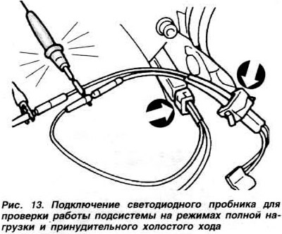
Checking the operation of the subsystem at full load and forced idle
Start the engine at idle. Move manually switch 1 (pic. 9) full load. In this case, the idle speed should first increase, and then begin to fluctuate. If not, check the full load switch as above. Warm up the engine to normal operating temperature. Disconnect the connector at the bottom of the throttle body (pic. 13). Connect both parts of the connector with adapters and connect the LED probe to them, as shown in fig. 13. When the engine is idling, the probe LED should be on. Raise the engine speed to approximately 3000 rpm and release the accelerator pedal. If the subsystem is operating normally in the forced idle mode, the probe LED should turn off momentarily.
Checking the electrical circuits of the KSUD
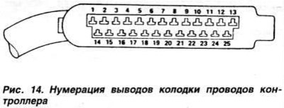
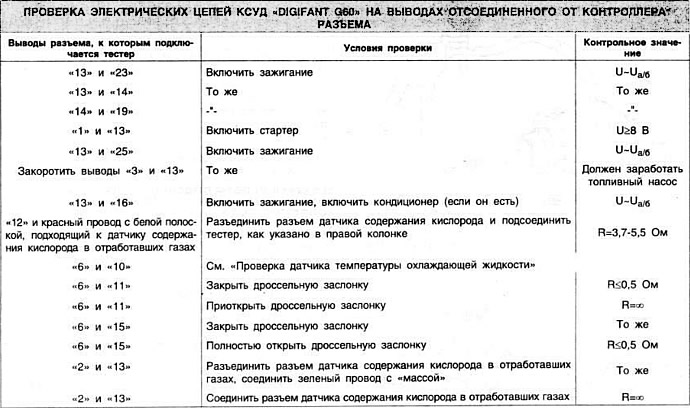
Check the state of charge of the battery. Make sure fuse #18 is good. fuel pump and relay subsystem, as well as the integrity and reliability of wire connections «masses». Make sure the ignition is off and disconnect the controller connector. Attaching a digital tester to the terminals of the connector disconnected from the controller (in voltmeter and ohmmeter mode), check the compliance of its indications with those indicated in the table. The numbering of the terminals of the controller wire block is shown in fig. 14.
Visitor comments