
Fuel is taken by an electric submersible roller pump installed in the fuel tank in one unit with a fuel level sensor. Brand and catalog number of the fuel pump: Bosch 0 580 453 012.
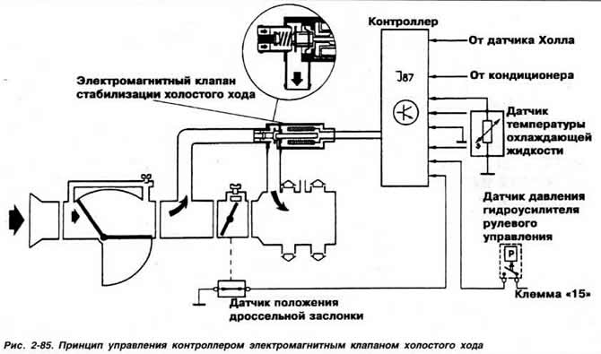
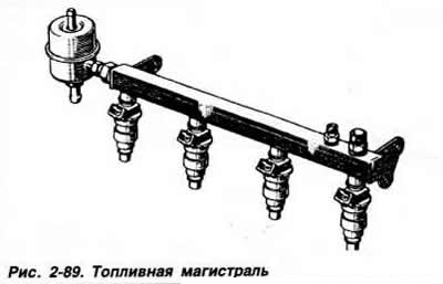
Fuel through the Bosch brand filter, installed at the rear of the car, is supplied to the injectors. The pressure of the fuel supplied to the injectors is maintained at a predetermined level depending on the pressure in the inlet pipeline by a fuel pressure regulator calibrated to a pressure of 3 kgf/cm2 (pic. 2-85). The supply of the required amount of fuel and maintaining a constant quality of the working mixture are provided by the controller. which receives and processes the following information:
- intake air quantity and temperature:
- rotational speed and angular position of the engine crankshaft;
- coolant temperature;
- throttle position (to determine the operating mode of the engine).
On vehicles with engine «RV» and engine «2E» without a catalytic converter, the controller is located in the engine compartment behind the bulkhead reinforcement.
Make and part number: vehicles with manual transmission: Bosch 0 261 200 298: vehicles with automatic transmission: Bosch 0 261 200 299. On vehicles with engine «2E» with a catalytic converter, the controller is located under the instrument panel on the right. Make and type VW Audi Digifant DFI. Depending on the received signals, the controller simultaneously controls the opening of injectors that spray fuel in front of the intake valves.
To prevent air leakage by the air flow meter, the entire air path for supplying air to the engine is completely sealed.
To clean the air entering the cylinders, an air filter with a dry paper replaceable element of the Mann C 31152 brand is used, with an incoming air heater, the damper of which opens at an air temperature above 30°C and closes at an air temperature below 20°C. The frequency of replacement of the replaceable element: every 30,000 km of run.
When starting a cold engine, the engine KCM controller «RV» issues commands to increase the duration of the opening of the fuel injectors, and on the engine «2E» an additional amount of fuel is injected at the commands of the controller by the starting injector.
The degree of enrichment of the mixture is determined by the controller depending on the temperature of the coolant, the operating time of the starter and the speed of the crankshaft.
When starting both a cold and a hot engine, the controller receives an electrical signal from the terminal «50» starter about the time of its inclusion, as well as a signal from the coolant temperature sensor. After processing them, the controller calculates the duration of the injectors opening, which ensures a reliable engine start, regardless of its temperature state.
During engine warm-up, the controller determines the required degree of enrichment of the fuel-air mixture based on information from the coolant temperature sensor and accordingly increases the open time of the fuel injectors (engine «RV») or starter injector (engine «2E»). At the same time, the controller adapts the idle speed control solenoid valve control current to the coolant temperature. The valve flap is covered to some extent. As a result, the combustible mixture is enriched, which allows the engine to idle at an accelerated speed.
When the engine is idling, the controller receives a crankshaft speed signal from the Hall sensor. built into the ignition distributor, as well as an engine load signal from the idle switch and the full load switch (engine «RV») or throttle position sensor (engine «2E») and compares the received information with the programmed idle speed value. On the engine «2E» a potentiometric type throttle position sensor is installed on the throttle valve axis and sends a signal to the controller about the engine load. On the engine «RV» position type sensors are installed on the throttle valve axis. The signals from the sensors are used to determine the mode of operation of the engine (idle or full throttle). If the crankshaft speed deviates from the programmed value, the controller increases or decreases the control signal current. issued to the idle speed stabilization solenoid valve, the stem of which accordingly changes the flow area of the bypass channel, made parallel to the throttle valve. This leads to an increase or decrease in idle speed. The principle of controlling the controller with an idle solenoid valve is shown in fig. 2-85.
On vehicles with air conditioning and power steering, the idle speed is increased by 100 rpm by controller commands.
The design of some devices of the injection control subsystem
Fuel pressure control.The diaphragm pressure regulator maintains a constant injection pressure regardless of the vacuum in the intake manifold. It consists of a metal case 1 (pic. 2-86), diaphragms 2. springs 3, vacuum intake pipe 4 from the inlet pipeline, fuel supply pipe 5, drain pipe 6 and valve 7.
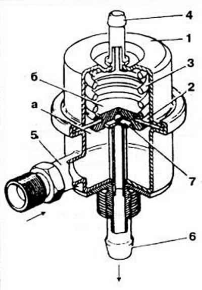
Pic. 2-86. Cutaway fuel pressure regulator:
1 - body;
2 - diaphragm;
3 - spring;
4 - vacuum intake pipe;
5 - fuel supply pipe;
6 - drain pipe;
7 - valve.
If the fuel pressure in the chamber «A» the force of spring 3 becomes greater, valve 7 opens and excess fuel is drained into the tank. Camera «b» connected by a hose to the inlet pipeline, depending on the vacuum in which the spring 3 acts on the valve 7 in such a way that the pressure difference between the chamber «A» and intake piping has always been constant. As a result, regardless of the engine load, the differential pressure supplied to the injectors remains unchanged. Solenoid fuel injectors. The dosing of the fuel injected into the engine intake channel is carried out by electromagnetic nozzles installed in front of the intake valves. The nozzle brand Bosch catalog number 0 280 150 757 consists of the following main parts: body 1 (pic. 2-88), needle valve 2. spring 3, armature 4, electromagnetic winding 5, block 6 and filter 7. The needle valve at rest is pressed against the seat by a spring, and opens with an electromagnet and armature. When voltage pulses are received from the controller, a magnetic field is created in the electromagnet winding, the armature is retracted, the needle valve moves away from the seat, and fuel under pressure is sprayed through the annular calibrated slot.
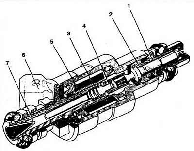
Pic. 2-88. Sectional view of electromagnetic injection nozzle:
1 - body;
2 - needle valve;
3 - spring;
4 - steel anchor;
5 - winding;
6 - block;
7 - filter.
The amount of fuel injected depends only on the duration of the opening of the injectors, determined by the controller based on information received from the sensor. The composition of the combustible mixture injected into the cylinders is the same, since the nozzles are connected in parallel and open and close at the same time. The injectors inject fuel twice for every revolution of the crankshaft. those. at the same time, only half of the amount of fuel required for the working stroke is injected.
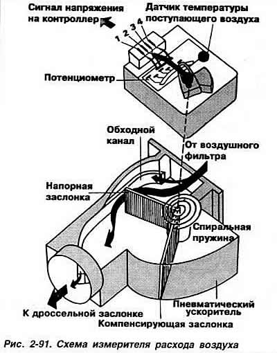
Difficult start, inability to start the engine, as well as its unstable idling, indicate a possible malfunction of the injectors. Air flow meter. The Bosch brand meter consists of the following main parts (pic. 2-90): housing, pressure damper 1, compensation damper 2, damper 3, potentiometer 4, intake air temperature sensor 5, bypass channel 6 and CO correction screw 7. Catalog number of meters installed at the factory 0 280 200 241. Spare parts 0 289 200 242.
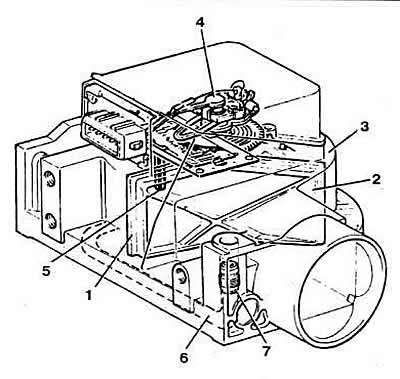
Pic. 2-90. Air flow meter:
1 - pressure valve;
2 - compensation damper;
3 - pneumatic damper;
4 - potentiometer;
5 - intake air temperature sensor;
6 - bypass channel;
7 - CO correction screw.
The action of the meter is based on the so-called medium resistance. It measures the force acting on damper 1, which the airflow entering the engine causes to rotate through a certain angle, overcoming the force of the coil spring. The moment of twisting of the spring is chosen as follows. so that the damper creates a slight pressure loss. To prevent swinging of the pressure damper under the influence of fluctuations in the flow of gases that occur in the inlet pipeline, there is a pneumatic damper 3. in which a compensation damper 2 is located, which has the same working surface as the pressure damper. Calm volume. as well as the gap between the compensating damper and the housing are selected so that the pressure damper is able to track rapid changes in air flow during acceleration.
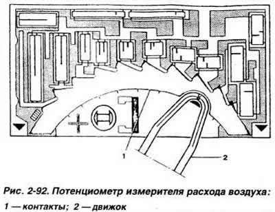
A potentiometer connected to the axis of the pressure flap converts the mechanical displacement of the pressure flap into a change in electrical voltage, which is transmitted to the controller for precise fuel dosing. The internal geometry of the meter provides a logarithmic correlation between the air flow and the angular position of the pressure damper. This allows you to accurately calculate the optimal composition of the combustible mixture for non-load engine operation. The potentiometer is installed in a sealed housing, from which moisture is completely removed. It consists of a ceramic base with a number of contacts (pic. 2-92) and several resistors whose resistance values are corrected by a laser. The resistance of the resistors is constant and does not depend on sudden temperature fluctuations in the engine compartment. The slider 2 is connected to the pressure gate and provides electrical connection with the contacts. To eliminate the influence of the battery voltage on the signal output by the potentiometer, the controller takes into account the difference between this voltage and the output voltage of the air flow meter.
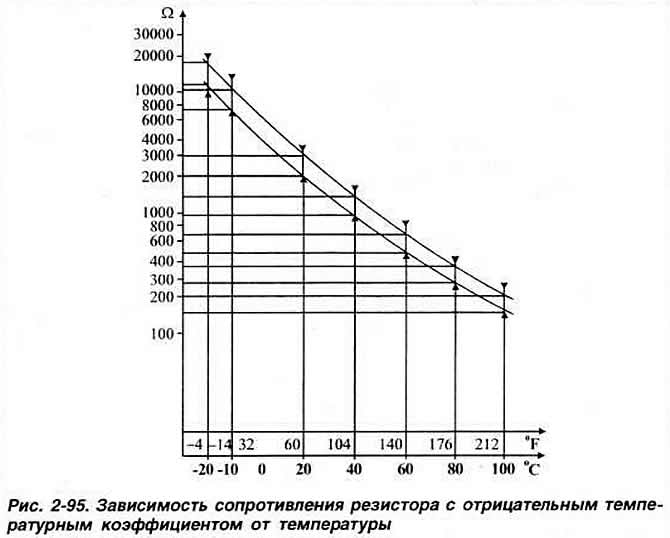
In parallel with the electrical circuit of the meter, an intake air temperature sensor is connected. It is a resistor with a negative temperature coefficient, i.e. its resistance decreases with increasing temperature. The signals coming from the sensor change the output signal of the meter depending on the temperature of the incoming air. If the engine does not start or starts with difficulty, stalls after starting, if the fuel consumption is too high, and the carbon monoxide content in the exhaust gases is not up to standard. This could be caused by a faulty intake air temperature sensor.
The bypass channel under the pressure flap is used for the passage of air at idle. Carbon monoxide content (SO) in exhaust gases, it is regulated by changing the flow area of the bypass channel with screw 7.
Sensor installed on the exhaust pipe of mufflers on vehicles with an engine «2E» with an exhaust gas converter, gives the controller information about the presence of oxygen in the exhaust gases.
A malfunctioning air flow meter can cause the following engine problems:
- the engine does not start or starts with difficulty;
- the engine starts and stalls;
- the engine is unstable at idle;
- the engine does not have sufficient throttle response;
- increased fuel consumption;
- the engine stalls in all modes;
- the content of carbon monoxide in the exhaust gases does not correspond to the norm;
- the engine does not develop full power.
throttle body (pic. 2-93) consists of the body itself 1. throttle valve 2. idle bypass channel 3 and idle air adjustment screw 4. The amount of air entering the engine is determined by the opening of the throttle 2. mechanically connected to the accelerator pedal. At idle, with the throttle closed, the air necessary for the formation of a combustible mixture enters the engine intake channel through the gaps between the edges of the throttle valve and bypass channel 3. Air quantity. passing through the bypass channel 3. and. therefore, the idle speed of the engine crankshaft is controlled by screw 4.
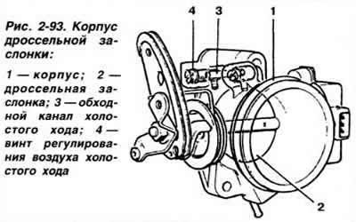
Pic. 2-93. Throttle body:
1 - body;
2 - throttle valve;
3 - idle bypass channel;
4 — the screw of regulation of air of idling
Idle stabilization valve. The solenoid valve of rotary type is installed in the air channel, made parallel to the throttle body, and ensures the constancy of the engine crankshaft speed at idle, changing the flow area of the air channel.
On the engine «RV» a VDO VAG valve is installed, catalog No. 037 906 457A. On the engine «2E» a VDO valve is installed.
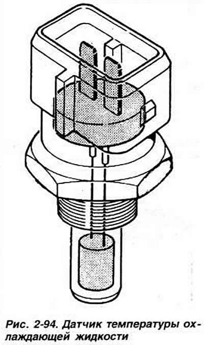
Coolant temperature sensor. During engine warm-up, the control unit provides enrichment of the combustible mixture based on an electrical signal from the coolant temperature sensor installed in the cylinder head. Sensor (pic. 2-94) is a negative temperature coefficient resistor. those. its resistance decreases with increasing temperature (pic. 2-95). If the engine does not start or starts with difficulty, stalls after starting, as well as with increased fuel consumption and abnormal CO content in the exhaust gases, it is necessary to check the serviceability of the coolant temperature sensor.
The relay of inclusion of the fuel pump.The tachometric relay is located in the mounting block installed under the instrument panel on the left. The pump power circuit is protected by a fuse located in the mounting block.
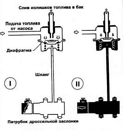
Pic. 2-87. The principle of operation of the fuel pressure regulator:
I - at idle, the fuel pressure is maintained at 2.0 kgf / cm2;
II - in full load mode, fuel pressure is maintained at 2.5 kgf / cm2.
Visitor comments