
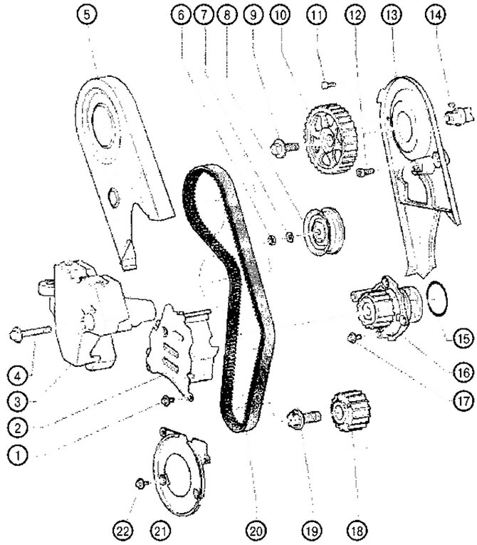
VC1.078. Timing drive for gasoline engines 1.6 l BGU, ALL, BCF:
1. Screw: 10 Nm
- Apply threadlocker
2. The middle part of the casing of the toothed belt
3. Engine mount bracket
4. Screw: 45 Nm
5. Upper part of the toothed belt cover
6. Screw: 23 Nm
7. Washer
8. Semi-automatic tension roller
9. Screw: 100 Nm
10. Camshaft pulley
- Mounting position determined by key
11. Screw: 10 Nm
- Apply threadlocker
12. Screw: 23 Nm
- Apply threadlocker
13. Rear toothed belt cover
14. Segment key
15. O-ring
- Replace with a new one
16. Coolant pump
17. Screw: 15 Nm
18. Crankshaft pulley
- There must be no oil on the contact surfaces of the toothed pulley and crankshaft
- Mounting possible in only one position
19. Screw: 90 Nm and tighten 90'
- Replace with a new one
- Do not grease
20. Toothed belt
- Before removing, mark the direction of movement of the belt with chalk or a felt-tip pen
- Check wear
21. Lower casing of the toothed belt
22. Screw: 10 Nm
- Apply threadlocker
Removing
1. Remove the engine cover.
2. Remove poly V-belt.
3. Remove the retainer.
4. Disconnect the upper hose from the expansion tank of the cooling system.
5. Remove the expansion tank and put it aside.
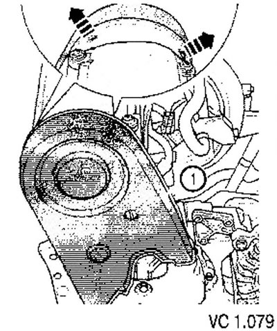
6. To remove the top part of a casing of a gear belt for what to carry out the following actions.
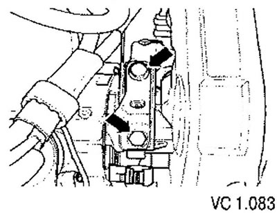
- Turn fixing screw (1) so that its slot is vertical.
- Push up the fasteners (arrows) and remove the upper part of the toothed belt cover.
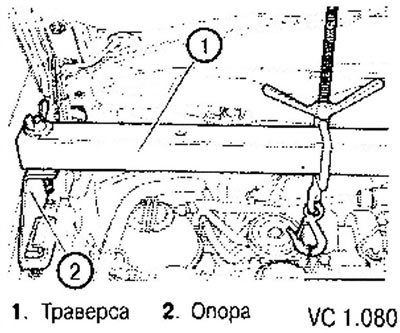
7. Install the traverse (1) with support (2) and hang the engine so that its supports are not loaded.
8. Remove the bottom soundproof casing.
9. Remove damper (pulley) from the hub of the crankshaft pulley.
10. Remove the middle and bottom parts of the toothed belt guard.
11. Unscrew the lower fixing bolt (1) engine mount bracket.
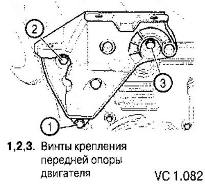
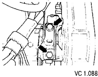
12. Unscrew the fixing bolts of the engine support (arrows) and completely remove the support.
Carefully! When hanging the engine using a traverse, special attention must be paid to ensure that no components / hoses are damaged, twisted or torn from their places.
13. Raise the motor with the yoke as far as possible, so that both upper mounting bolts can be loosened and unscrewed (2) And (3) engine mount bracket (see fig. VC1.082).
14. Remove the engine support bracket by lifting it up.
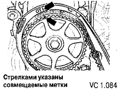
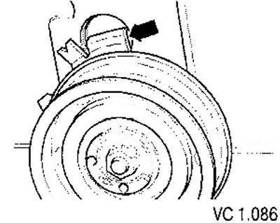
15. Rotating the crankshaft, set the camshaft pulley to the TDC position of the first cylinder.
The mark on the camshaft sprocket must align with the arrow on the toothed belt guard.
16. Mark the direction of travel of the toothed belt.
17. Loosen the tension roller and remove the toothed belt.
18. After that, slightly turn the crankshaft back.
Installation
When rotating the camshaft, the crankshaft must not be in the TDC position. Possible damage to valves and piston crowns.
1. Install the toothed belt on the crankshaft sprocket and on the water pump sprocket (observing the correct direction of the belt).
2. Install the camshaft in such a position that the marks on the toothed pulley and the toothed belt housing coincide.
3. Install the middle and bottom parts of the toothed belt guard.
4. Install the crankshaft pulley on the hub with new screws. Tightening torque: 10 Nm + 1/4 turn (90°).
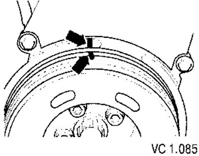
5. According to the marks on the crankshaft pulley, bring the crankshaft to the TDC position of the first cylinder (arrow).
6. Install the toothed belt on the tension roller and camshaft pulley.
Pay attention to the correct position of the tension roller in the cylinder head.
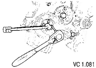
7. Tension toothed belt. To do this, using a special key (3) turn the eccentric counterclockwise until the arrow (2) will not be slightly higher risks (1) (the belt will be tightened).
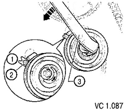
8. Repeat this action (belt tension with excess belt force) five times to ensure the belt is properly installed.
9. After that, loosen the belt so that the risk (1) and arrow (2) aligned.
10. Tighten the nut to 20 Nm.
11. Rotate the crankshaft two turns in the direction of engine rotation and set it back to the TDC position of the first cylinder. At the same time, the last 45' (1/8 turn) the crankshaft must rotate without stopping (and without increasing effort).
12. Check the belt tension again. Correct position: risk and arrow must be aligned.
13. Check the GII setting again. If the marks do not match, repeat the timing adjustment.
14. Install bracket (above) on the cylinder block and tighten both upper screws to 45 Nm.
15. Lower the motor to its final mounting position.
16. Install the lower fixing screw and tighten it to 45 Nm.
17. Install the engine mount assembly.
18. Using new screws, screw the support to the engine bracket (arrows), while lowering the engine with the help of a traverse so that the bracket comes into contact with the support. Tightening torque: 60 Nm and tighten 90' (1/4 turn).
19. Remove the traverse.
20. To establish the top part of a casing of a gear belt.
21. Install poly V-belt.
22. Install the expansion tank of the cooling system.
23. Install the bottom soundproof casing.
24. Install the engine cover.
Visitor comments