



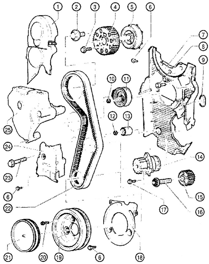
VC1.089. Timing drive of diesel engines:
1. Upper part of the timing belt cover
2. Screw 100 Nm
3. Screw 25 Nm
4. Camshaft sprocket
5. Hub with toothed ring
6. Screw 10 Nm
- replace
7. Rear timing belt cover
8. Screw 25 Nm
9. Sealing ring
- if there is any damage, replace
10. Nut 20 Nm + tighten by 1/8 turn (45°)
11. Tension roller
12. Nut 20 Nm
13. Runner roller
14. Water pump
15. Crankshaft toothed pulley
16. Screw 120 Nm + tighten by 1/4 turn (90°)
- replace
17. Screw 15 Nm
18. Lower part of the timing belt cover
19. Crankshaft pulley
- installation is possible only in one position (the holes are located with an offset)
20. Screw 10 Nm + tighten by 1/4 turn (90°)
21. Lid
22. Toothed belt
23. Screw 40 Nm + 1/2 turn (180°)
- replace
24. Middle part of the toothed belt protective cover
25. Engine retainer
Removal, installation and tensioning the timing belt
Since 05.2005, a modified engine mount has been used that does not require removal of the engine mount and fixing the engine when replacing the timing belt.
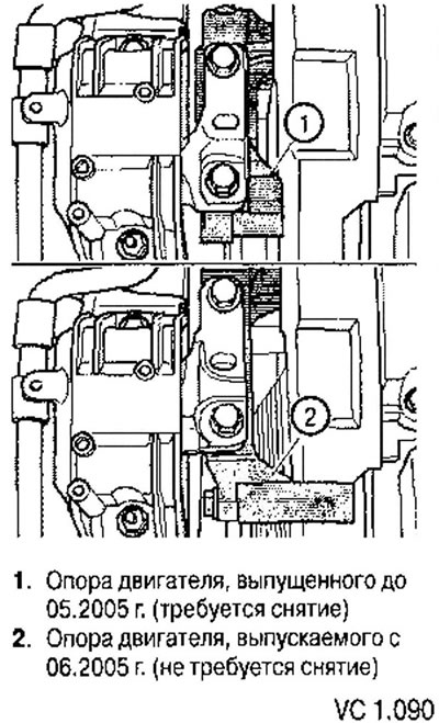
Removal, installation and tensioning of the timing belt for vehicles manufactured before 05.2005. (with a support installed near the engine)
Since the 2004 model year, a new timing belt tensioner roller has been installed.
The tensioner pulley has an additional internal hex key (arrow). To tighten or loosen the timing belt, use a socket wrench instead of a two-hole wrench. The order of work does not change.
Removal
Please note: the timing belt adjustment should only be performed on a cold engine, as the tensioner adjustment position changes depending on the temperature.
1. Remove the upper engine cover. Remove the engine cover by pulling it with a jerk first upwards (arrows A) and then forwards (arrow B) (to detach the rear mount).
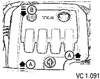
BJB engines (1.9 l, TDI, 77 kW, 105 hp, with pump-nozzle), BSU (1.9 l, TDI, 55 kW, 70 hp, with pump-nozzle)
2a. Remove the pipe connecting the charge air cooler and the intake manifold.
BLS engines (1.9 l, TDI, 77 kW, 105 hp)
26. Remove the pipe connecting the air intake pipe and the air damper drive motor (V157).
Continuation of the description of works for all engines
3. Unscrew the fuel filter bracket from the engine mount - arrows.
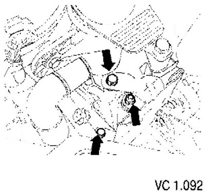
4. Unscrew the expansion tank of the cooling system and put it aside (the hoses remain connected).
5. Remove the poly V-belt.
6. Remove the tensioner retainer of the poly V-belt.
7. Remove the front right wheel arch liner.
8. Remove the pipe connecting the charge air cooler and the turbocharger.
9. Remove the flexible air intake hose connecting the turbocharger and the air filter. To prevent dirt from getting into the air tract, you need to plug the openings of the intake system with a clean rag.
10. Remove the crankshaft pulley.
11. Remove the lower and middle timing belt covers.
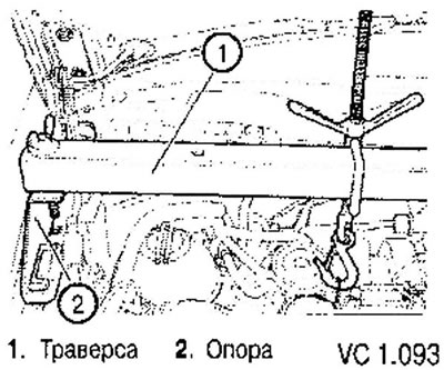
12. Install the crossbar with the stands and hang the engine by the eye without changing its position. If the timing belt is removed to remove the cylinder head, the crossmember should be installed with higher struts. This will provide enough space to remove the cylinder head.
13. Unscrew the support mounting bolts on the engine bracket and on the body (arrows) and completely remove the support.
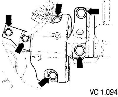
Caution! The support can only be removed after the engine has been supported using a crossmember.
The engine mount bracket fasteners may only be loosened after the mount has been removed.
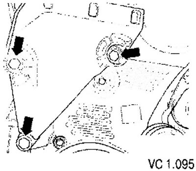
14. Raise the engine slightly using a crossmember to remove both upper bracket mounting bolts.
15. Lower the engine slightly using a crossbar to unscrew the lower bracket mounting bolt.
16. Remove the engine support bracket by moving it downwards.
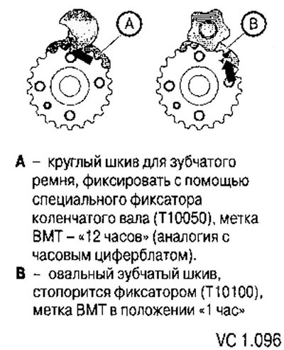
Please note: Some engines may be equipped with an oval crankshaft timing pulley. In this case, to determine the TDC of the first cylinder, it is necessary to install a special crankshaft locking device (manufacturer's marking: T10100).
Differences in crankshaft timing pulleys
[The information is posted on this resource VWMANUAL]
Engines with round or oval toothed crankshaft pulley
17. Set the crankshaft to the TDC position of the first cylinder. To do this, rotate the crankshaft until the mark on its toothed pulley and the toothed segment of the camshaft pulley are at the top. In this case, the mark on the camshaft pulley should coincide with the mark on the timing belt cover behind the pulley (arrow).
18. Secure the hub using the locking tool (3359). To do this, insert the locking tool into the hole in the cylinder head through the free arc-shaped concentric groove on the left side of the camshaft pulley.
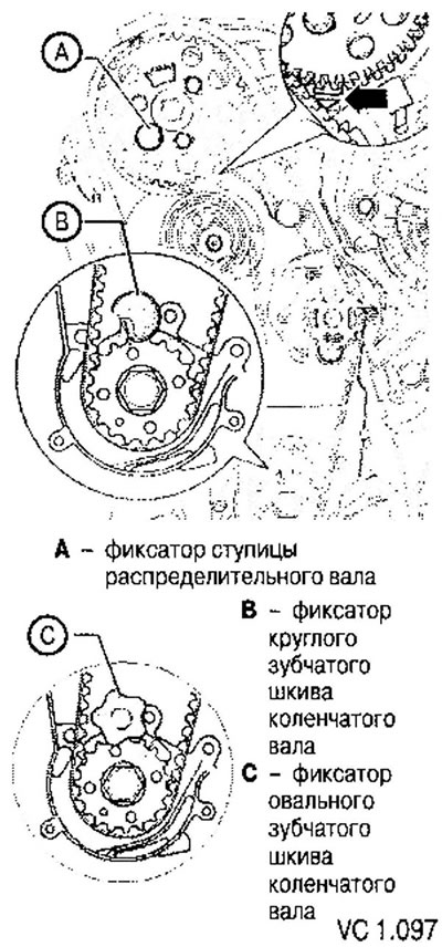
19. Secure the crankshaft pulley using the crankshaft locking tool (T10050 or T10100). To do this, you need to engage the teeth of the locking device with the teeth of the pulley.
20. Mark the direction of movement of the toothed belt.
Marks on the crankshaft timing pulley and on the crankshaft locking pin (T10050 or T10100) must match. In this case, the crankshaft locking pin (T10050 or T10100) must fit into the hole of the sealing flange.
Continuation of the description of works for all vehicles
21. Loosen the mounting screws (1) of the camshaft pulley so that it can rotate in concentric grooves relative to the hub, which is fixedly connected to the camshaft.
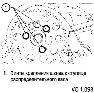
22. Loosen the tension roller mounting nut.
23. Rotate the timing belt tension roller using a special key (can be made according to the dimensions of the holes in the tensioner hub) counterclockwise until the tension roller can be locked using a suitable locking rod.
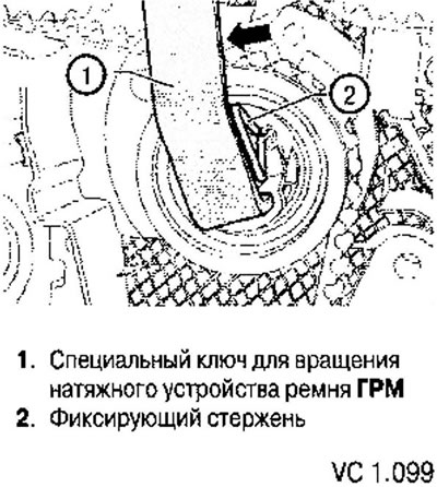
24. Turn the tensioner with a special key clockwise until it stops and tighten the fastening nut (3) by hand.
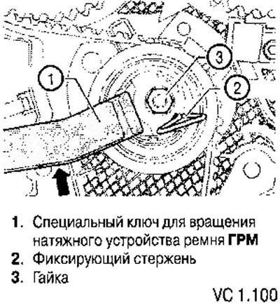
25. Remove the toothed belt first from the coolant pump pulley, and then from the other toothed pulleys.
Installation
Initial settings:
- The camshaft is secured with a locking tool (3359).
- Secure the crankshaft with a locking device (T10050 or T10100).
- The tension roller is secured with a lock (2) and fixed to the right stop.
1. Turn the camshaft pulley so that it occupies the middle position in the concentric grooves (arrows).
2. Install the toothed belt on the crankshaft pulley, on the tension roller, on the camshaft pulley and on the running roller.
3. Lastly, install the belt on the coolant pump pulley.
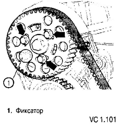
4. Ensure the proper position of the tension roller in the rear timing belt housing (arrow).
5. Loosen the tension roller fastening nut and remove the retainer.
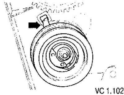
6. Carefully turn the tensioner roller clockwise with a two-hole nut wrench until the pointer is in the middle of the hole in the base (arrow). The mounting nut should not turn.
7. While holding the tension roller in this position, tighten the fastening nut as follows: 20 Nm and turn further by 1/8 of a turn (45°).
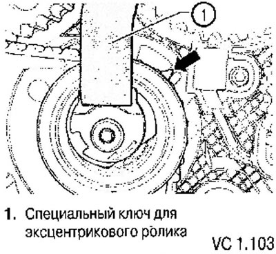
8. Install the camshaft timing pulley retainer with pins as shown in the figure.
9. Apply force to the retainer in the direction indicated by the arrow to hold the toothed pulley.
10. Tighten the camshaft pulley mounting screws (1) in this position to a torque of 25 Nm.
11. Remove the camshaft hub locking pin and crankshaft locking pin (T10050 or T10100).
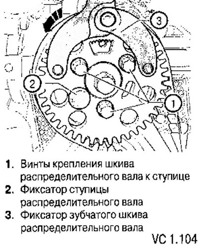
12. Turn the crankshaft two revolutions so that the piston of the 1st cylinder is in the 8th position, close to TDC.
13. Fix the camshaft hub with the lock (2) while rotating the crankshaft in the working direction.
14. Check whether the crankshaft can be locked in this position with a locking device (T10050 or T10100). If the crankshaft cannot be fixed, then the following steps must be performed.
- Loosen the camshaft pulley mounting screws (1).
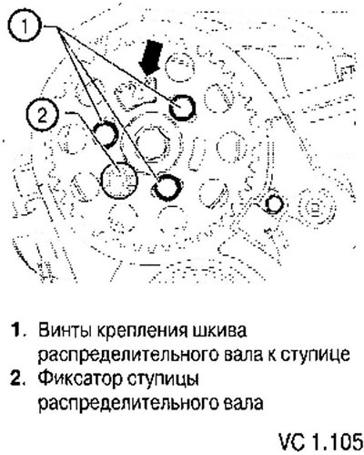
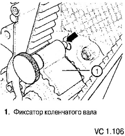
- Turn the crankshaft slightly in the opposite direction until the locking pin is almost at the corresponding hole in the crankshaft cover (arrow).
- Rotate the crankshaft in the working direction so that the locking pin enters the hole during rotation.
15. Install the camshaft timing pulley retainer with pins as shown in the figure.
16. Apply force to the retainer in the direction indicated by the arrow to hold the toothed pulley.
17. Tighten the camshaft pulley mounting screws (1) in this position to a torque of 25 Nm.
18. Remove the camshaft hub locking pin and crankshaft locking pin (T10050 or T10100).
19. Turn the crankshaft two revolutions so that the piston of the 1st cylinder is in a position close to TDC.
20. Recheck the possibility of fixing the crankshaft.
21. Install the engine mount onto the cylinder block and tighten the mounting screws (arrows) to a torque of 40 Nm + 1/2 turn (180°). Before installing the engine mount, all mounting bracket screws must be tightened to the specified torque.
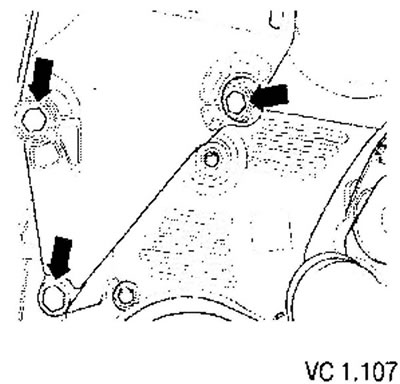
22. Secure the engine mount to the body (replace the screws at the same time).
- Tightening torque of M8 screws: 20 Nm + 90° (1/4 turn).
- Tightening torque of M10 bolts: 40 Nm + 90° (1/4 turn).
23. Screw the support to the bracket on the engine. To do this, properly align the mounting surfaces by moving the engine using a crosshead.
- Tightening torque: 60 Nm + 90° further (1/4 turn).
24. Install the middle and lower timing belt covers.
25. Install the crankshaft pulley onto the hub.
- Tightening torque: 10 Nm + 90° further (1/4 turn).
27. Install the upper timing belt guard.
28. Install the pipes connecting the charge air cooler to the turbocharger, and the charge air cooler to the intake manifold.
29. Install the front right fender liner.
Visitor comments