
Attention! This manual does not provide a detailed description of the timing belt replacement for 1.9 liter diesel engines. Below are just the basic steps for installing a toothed belt.
1. Set the piston of cylinder No. 1 to TDC.
2. Mark the direction of rotation of the toothed belt.
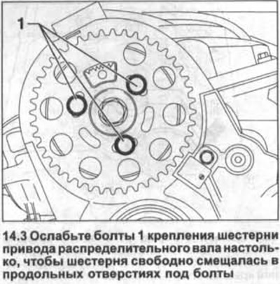
3. Loosen the bolts 1 for fastening the camshaft drive gear so that the gear moves freely in the longitudinal holes for the bolts (see illustration).
4. Loosen the tightening nut of the toothed belt tension roller.
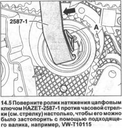
5. Turn the tension roller counterclockwise with the HAZET-2587-I trunnion wrench (see arrow in illustration) enough that it can be locked with a suitable roller, such as VW-T10115.
6. Turn the trunnion wrench fully clockwise without removing the locking roller and tighten the roller nut by hand.
Attention! On vehicles with a 2.0 liter engine, turning the toothed belt tensioner should be done with a hex socket wrench. The use of a trunnion key is permissible only in the absence of an end wrench.
7. Remove the toothed belt. The toothed belt is first removed from the water pump drive gear.
Installation
8. Install the gear on the camshaft so that the bolts in its longitudinal holes are in the center.
9. Lay the toothed belt on the crankshaft gear, tension roller, camshaft gear, idler roller. Lastly, the belt is placed on the water pump drive gear.
10. Make sure the lug on the idler pulley fits into the rear timing cover housing.
11. Loosen the nut securing the toothed belt tension roller and remove the thrust pin.
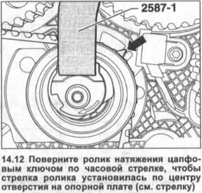
12. Turn the tension roller clockwise with a trunnion wrench until the arrow on the roller is centered on the hole in the base plate (see arrow in illustration). Make sure that the roller fastening nut does not also turn.
13. Hold the tension roller in this position and tighten its fastening nut with a force of 20 Nm, and then tighten it by 45° (1/8 turn).
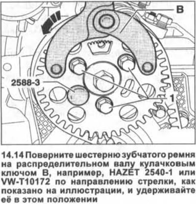
14. Turn the timing belt gear on the camshaft with a cam wrench B. For example, HAZET 2540-1 or VW-T10172 in the direction of the arrow as shown in the illustration and hold it in this position.
15. Tighten the gear mounting bolts in this position with a force of 25 Nm.
16. Remove the thrust roller and remove the retainer from the gear on the crankshaft.
17. Turn the crankshaft two turns in the direction of engine rotation (clockwise) and again set the piston of cylinder No. 1 to TDC. Before completing the second revolution, insert the HAZET 2588-3 thrust roller (see illustration 14.14).
18. Verify that the crankshaft can be locked using the locking device that is installed on the toothed belt gear on the crankshaft.
If the protrusion of the locking device does not fit into the sealing flange, then proceed as follows:
19. Remove the locking device and turn the crankshaft so that the toothed belt gear hub on the camshaft can be fixed with a thrust roller.
20. Loosen the timing belt gear bolts on the camshaft.
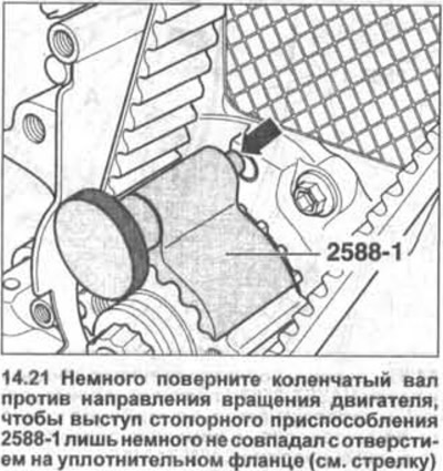
21. Rotate the crankshaft slightly against the direction of engine rotation so that the projection of the locking device 2588-1 is only slightly aligned with the hole in the sealing flange (see arrow in illustration).
22. Now rotate the crankshaft in the direction of engine rotation so that the protrusion of the locking device in the direction of rotation enters the hole in the sealing flange.
23. Turn the toothed belt gear on the camshaft with a cam wrench B, for example, HAZET 2540-1 in the direction of the arrow, as shown in illustration 14.14, and, holding it in this position, tighten the gear mounting bolts with a force of 25 Nm.
24. Remove the thrust roller and remove the retainer from the gear on the crankshaft.
25. Turn the crankshaft two turns in the direction of engine rotation (clockwise) and again set the piston of cylinder No. 1 to TDC.
26. Fasten the engine mount bracket to the cylinder block by tightening the mounting bolts to 45 Nm.
27. Secure the engine mount with new bolts to the body.
The tightening torque of the M8 bolts is 20 Nm + 90°turn (1/4 turn), tightening torque for M10 bolts - 40 Nm + 90°turn (1/4 turn).
28. Bolt the support and the engine mount bracket by tightening them with a force of 60 Nm / 90°turn (1/4 turn).
29. Reinstall the middle and bottom parts of the protective cover of the gas distribution mechanism.
30. Install on the crankshaft and bolt the accessory drive belt pulley.
Pulley bolt tightening torque 10 Nm + 90°turn (1/4 turn).
31. Lay the ribbed belt, see the relevant chapter.
32. Reinstall the top of the timing cover.
33. Reinstall the connecting hoses of the charge air cooling radiator/turbocharger and the charge air cooling radiator, intake manifold.
34. Install the fender liner in the right wheel arch.
35. Install lower motor guard and upper guard.
36. Reinstall the coolant expansion tank.
Visitor comments