



The exhaust and intake camshafts are connected to each other by a single-row roller chain.
Through the engine control unit, the ignition timing angle and, accordingly, the position of the intake camshaft can be constantly changed using a valve regulator in accordance with the operating loads on the engine.
The valves are driven by roller rocker arms on hydraulic support elements (see illustration 10.0)
To remove the cover, you need to unscrew the bolts (see arrows in illustration A), release it from the fastening on the central part of the lid and move it upwards.
When installing the cover, it should be especially carefully joined to the central part, and then secured with bolts at the top.
Tightening of the roller support plate mounting bolts is performed in sequence from 1 to 5 with the application of a force of 10 Nm (see illustration B).
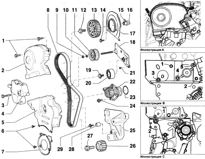
Timing drive. Cars with petrol engine 110 kW (150 hp) AXW
1 - bolts. Tightening torque 10 Nm. Before installation, lubricate with protective paste
2 - upper cover of the timing drive.
3 - bolt. Tightening torque 45 Nm
4 - Engine mount bracket
5 - central part of the timing cover
6 - bolts. Tightening torque 10 Nm. Before installation, lubricate with protective paste
7 - lower part of the timing cover
8 - timing belt. If the belt is to be reinstalled after removal, mark the direction of its rotation with chalk or a felt-tip pen before removal. Check the condition of the timing belt
9 - nut. Tightening torque 23 Nm
10 - spacer washer
11 - semi-automatic tension roller
12 - bolt Tightening torque 65 Nm
13 - camshaft gear. The position of the gear on the shaft is fixed with a key
14 - bolt. Tightening torque 10 Nm
15 - landing key. Make sure the fit is secure
16- camshaft
17 - rear cover of the timing drive
18 - tension roller support plate
19 - bolt. Tightening torque 40 Nm
20 - guide roller
21 - bolt. Tightening torque 10 Nm
22 - water pump
23 - O-ring. To be replaced after each dismantling
24 - bolt. Tightening torque 10 Nm
25 - support plate. When installing the plate, first screw in and tighten bolts 1 with a force of 40 Nm, and then bolts 2 with a force of 15 Nm (see illustration C)
26 - toothed belt pinion on the crankshaft. The pinion can only be installed in one position. The mating surfaces of the pinion and crankshaft must be degreased before installation.
27 - bolt for fastening the toothed belt gear to the crankshaft. Tightening torque 90 Nm + 90° turn (1/4 turn). The bolt must be replaced after each dismantling. Lubrication of the bolt thread is not allowed
28 - calming roller
29 - bolt. Tightening torque 25 Nm
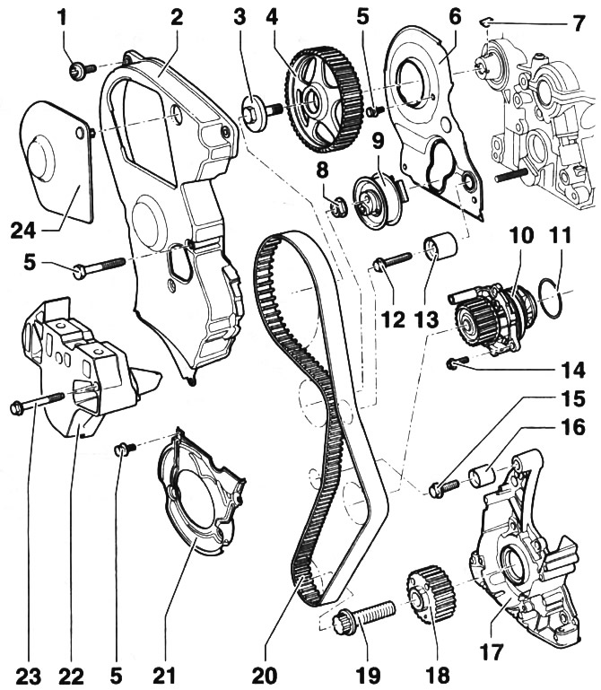
Timing drive. Cars with a 2.0-liter petrol engine and a power of 110 kW (150 hp) BLR/BLX/BLY
1 - bolt. Tightening torque 10 Nm
2 - upper cover of the timing drive.
3 - bolt. Tightening torque 65 Nm 4 - camshaft gear. The position of the gear on the shaft is fixed with a key
5 - bolt. Tightening torque 10 Nm
6 - rear cover of the timing drive
7 - landing key. Make sure the fit is secure
8 - nut. Tightening torque 26 Nm
9 - semi-automatic tension roller
10 - water pump
11 - O-ring. To be replaced after each dismantling
12 - bolt. Tightening torque 25 Nm
13 - calming roller
14 - bolt. Tightening torque 15 Nm
15 - bolt. Tightening torque 35 Nm
16 - calming roller
17 - sealing flange
18 - toothed belt pinion on the crankshaft. The pinion can only be installed in one position. The mating surfaces of the pinion and crankshaft must be degreased before installation.
19 - bolt for fastening the toothed belt gear to the crankshaft. Tightening torque 90 Nm + 90° turn (1/4 turn). The bolt must be replaced after each dismantling. Lubrication of the bolt thread is not allowed
20 - timing belt. If the belt is to be reinstalled after removal, mark the direction of its rotation with chalk or a felt-tip pen before removal. Check the condition of the timing belt
21 - lower part of the timing cover
22 - Engine mount bracket
23 - bolt. Tightening torque 45 Nm
24 - cover of the opening on the upper part of the protective cover of the timing drive
Visitor comments